Modelsvit M-17 Stratosfera
'Mystic-A'
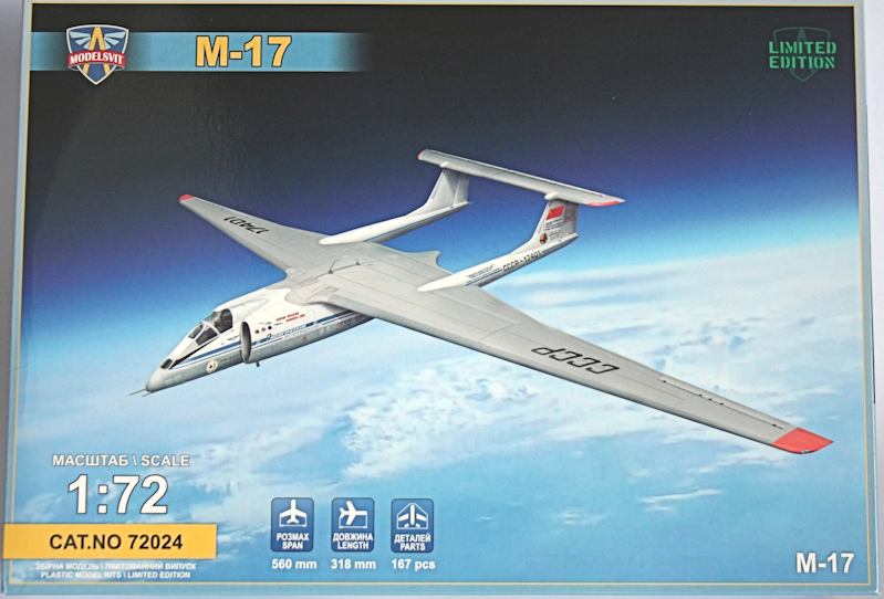
Impressive box art showing the record-breaking second prototype at altitude.
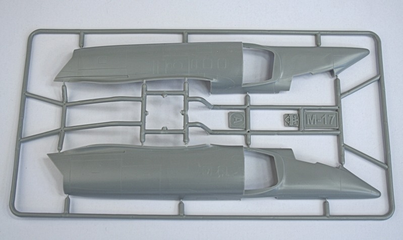
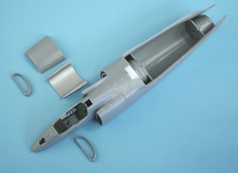
Fuselage halves with fine engraved panel detail.
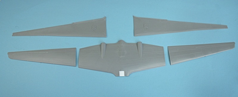
Wing lower halves - complete with reflex laminar flow shape.
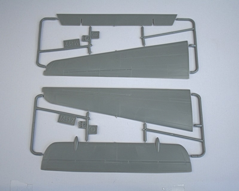
Upper wing halves and tailplane.
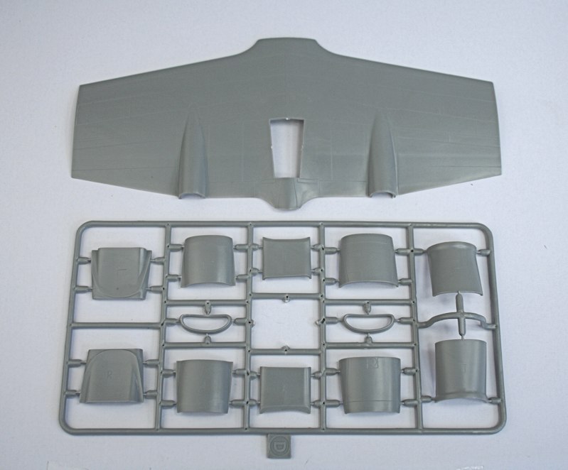
Upper wing centre section and intakes.
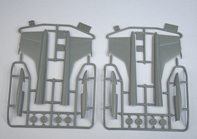
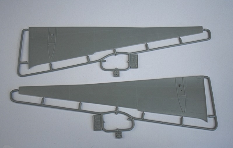
Tail booms and fins.
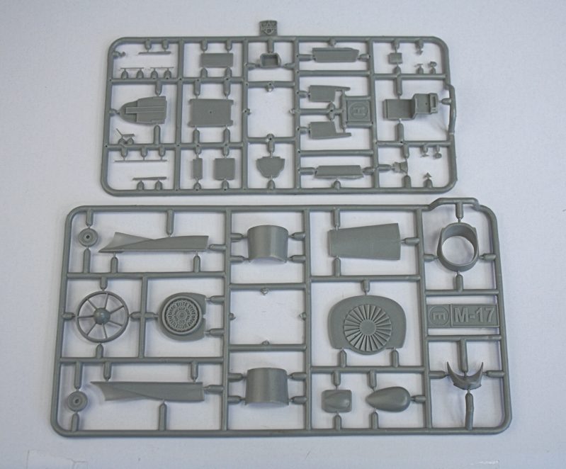
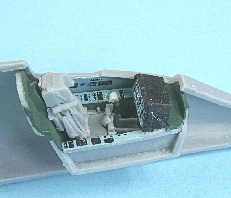
Cockpit and engine parts.
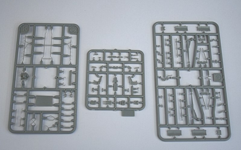
Parts for the access ladder, 22-part K-36 ejection seat and landing gear.
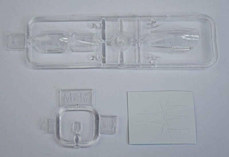
A coice of two canopies - open or closed - plus canopy masks.
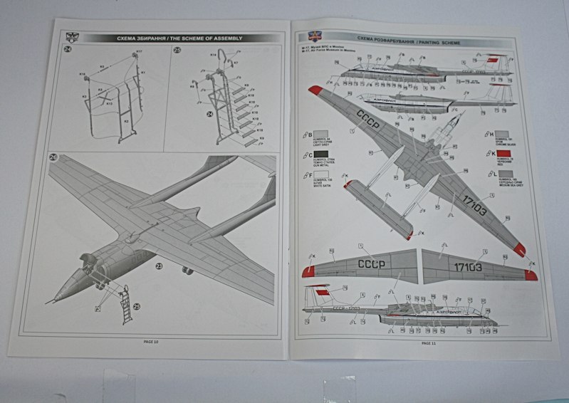
22-page instruction booklet.
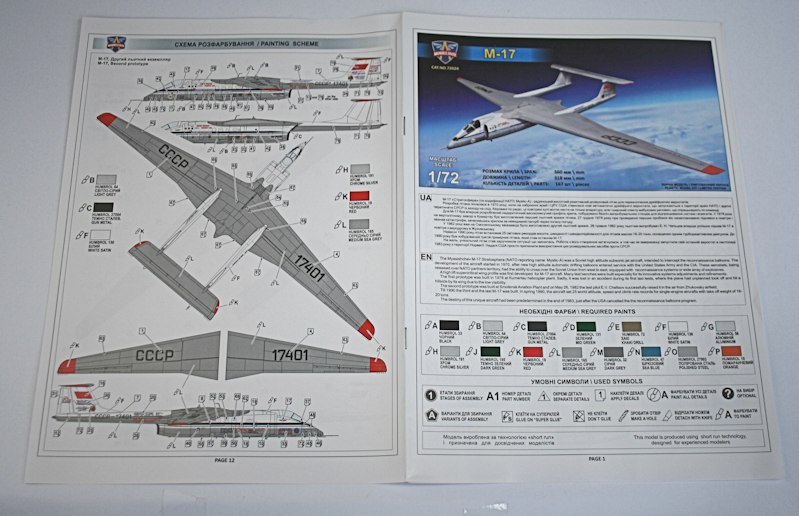
Painting and decal placement guide - with colours matched to Humbrol paints.
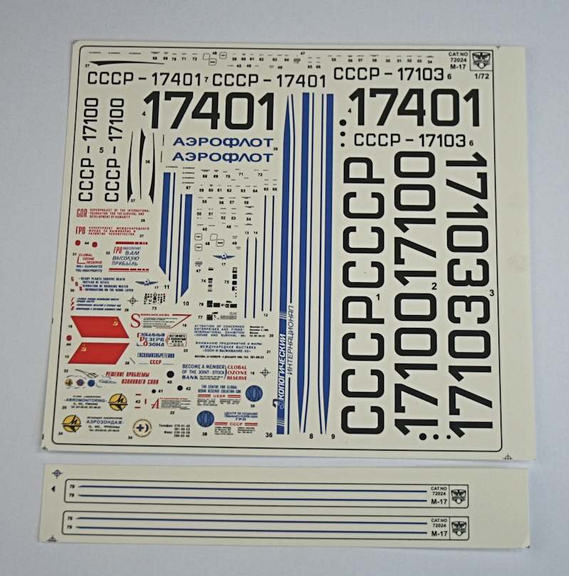
Comprehensive decal sheet with markings for CCCP-17103 (now at Monino)
and record-breaking second prototype CCCP-17401.
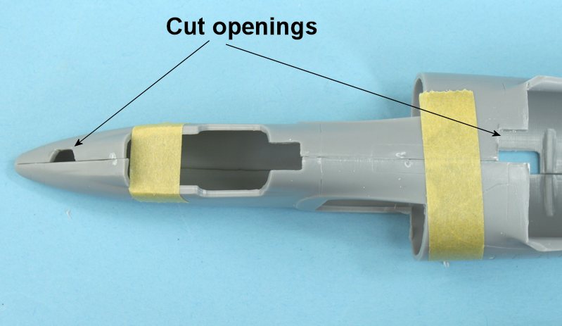
Opening have to be cut out for the version I am making.
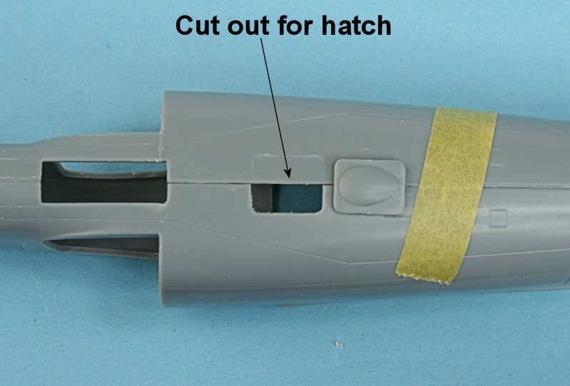
This opening has to be cut out for both versions - to fit an antenna hatch.
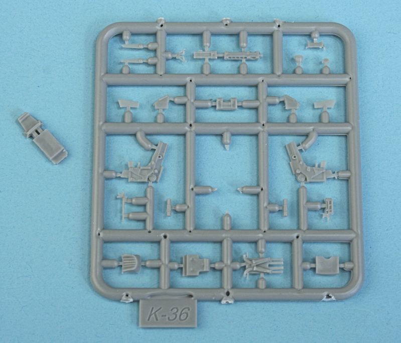
The K-36 ejection seat is made up from 23 tiny parts!
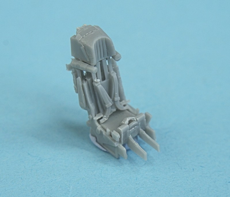
The made up seat (minus the firing handle - exqusite detail!
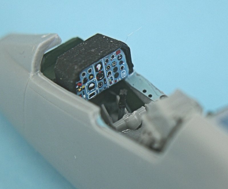
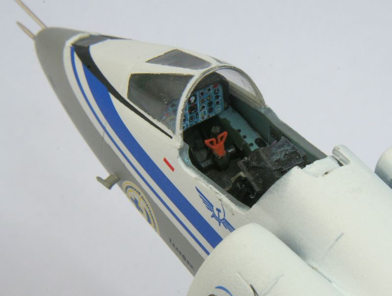
Decals are provided for the instrument panel......
.... and the side consoles (the seat is in place tempoarily).
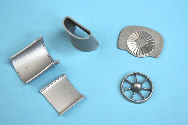
Component parts of the bifurcated intakes and engine compressor face.
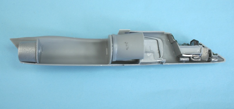
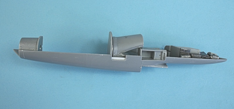
There's a lot to cram into the fuselage before the halves can be joined - from left to right :- engine exhaust assembly,
engine comressor and bifurcated intake assembly, outer intake duct, nosewheel well assembly, assembled cockpit
and camera/star tracker. Plus the 14g weight recommended in the instructions.
Underside view of the crammed left fuselage half.....
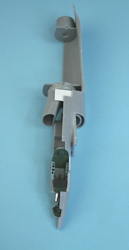
.... and a top view.
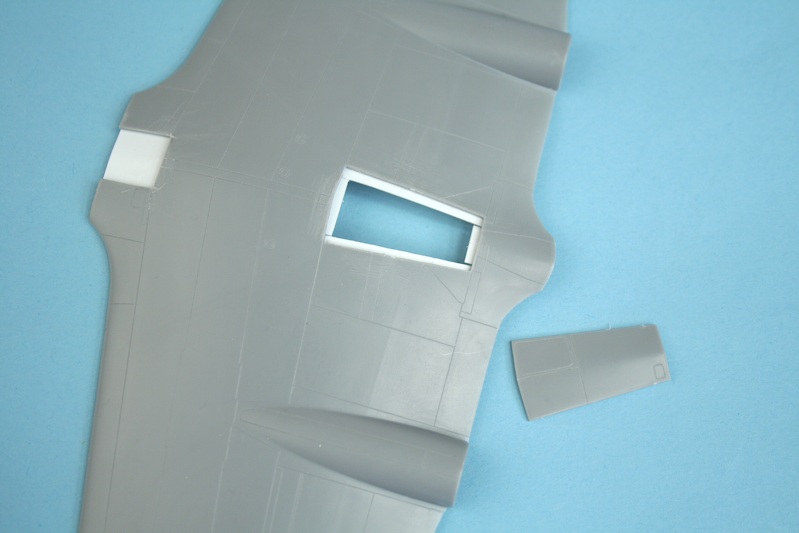
The wing centre section has a 'hatch' - I don't know why it's a separate part?
I have made a 'ledge' from white plastic card for it to sit on when it is fitted in place.
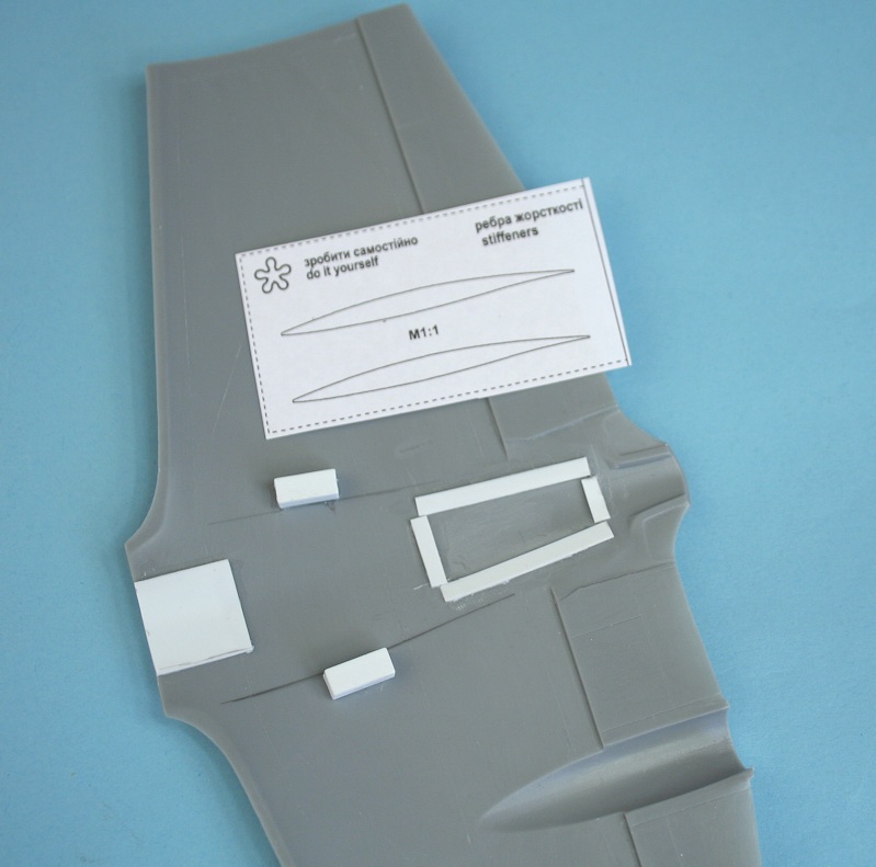
Modelsvit ask you to make to two ribs for the wing roots to (presumably to reduce flexing(?) and provide templates.
I've just added blocks of square section plastic card - which is easier and does the same job.
The top hatch is glued in place onto its plastic card ledge.
The wing components cleaned up ready for assembly.
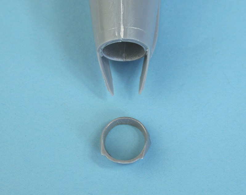
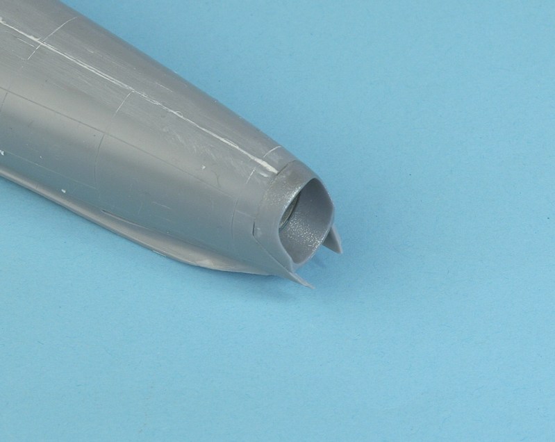
Engine intake assembly - the separate lips make for an easy demarcation line inside the intake.
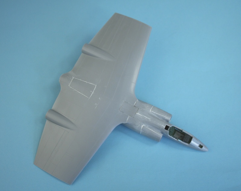
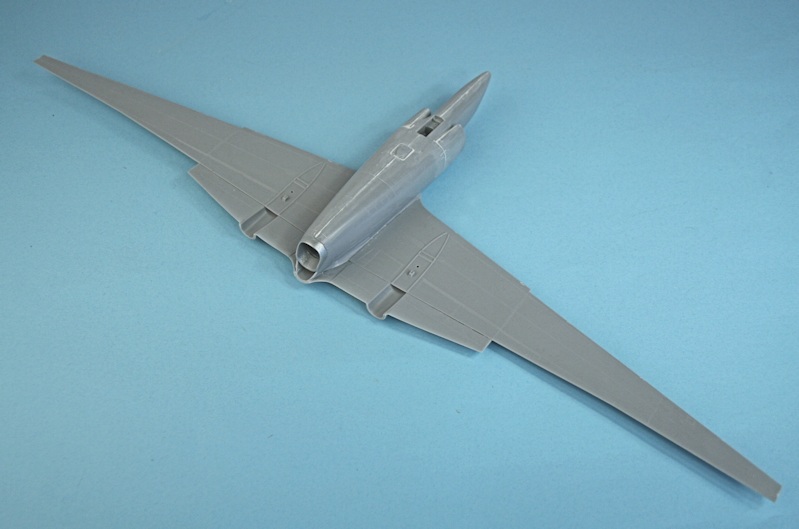
The wing centre section attached - it looks like something out of Star Wars or Batman.
Underside view showing the bulged hatch and wing root 'stiffeners'.
The rear end needs to be 'pinched in' a bit more - use part E11 to get the right shape. - I had to remove the wing centre section.
Part E11 glued in place - the rear end is now correct.
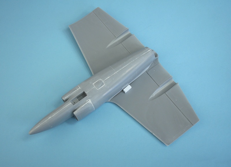
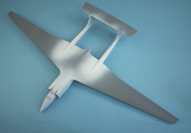
Upper wing centre section re-attached and lower outer wing panels attached - note the 'pinched-in' jetpipe.
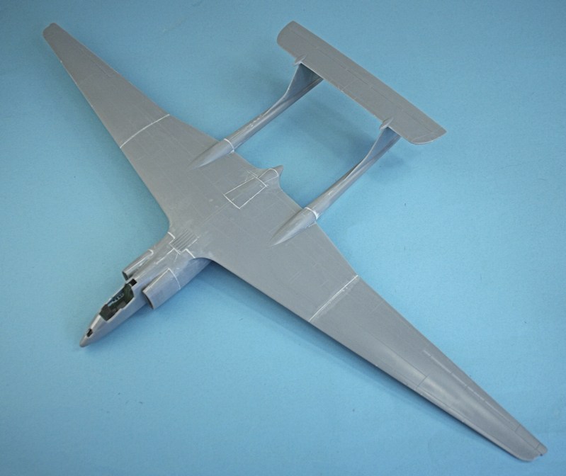
Top view of the wing layout.
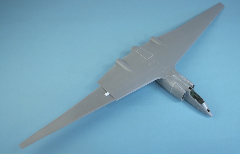
Port upper outer wing added - note the spacer on the starboard side.
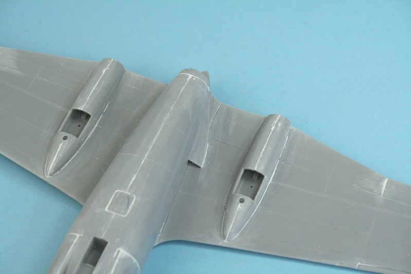
The wing root intakes and wheel well sponsons needed a bit of 'fettling'.
The rear of the wing root intakes are open...........
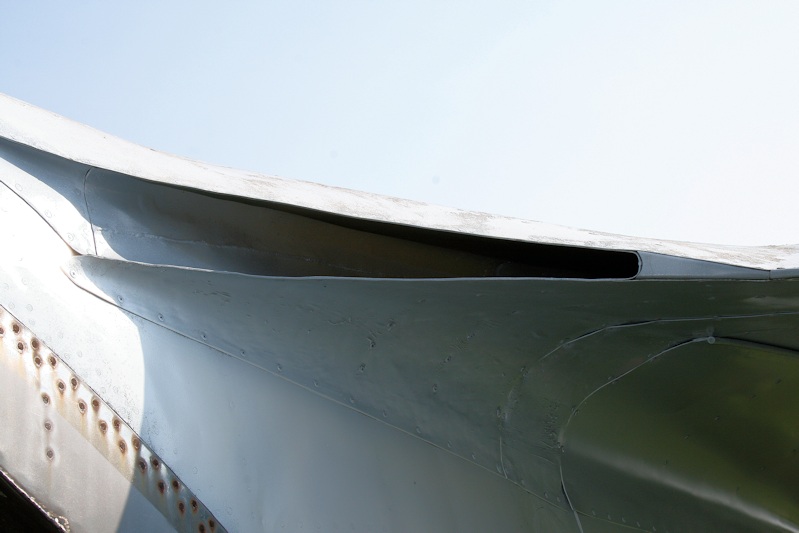
.... as my photo of the real thing shows.
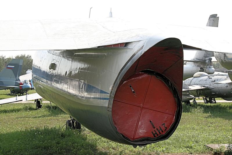
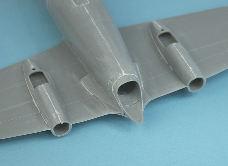
Rear end with 'pen knib' fairing and open outlets.
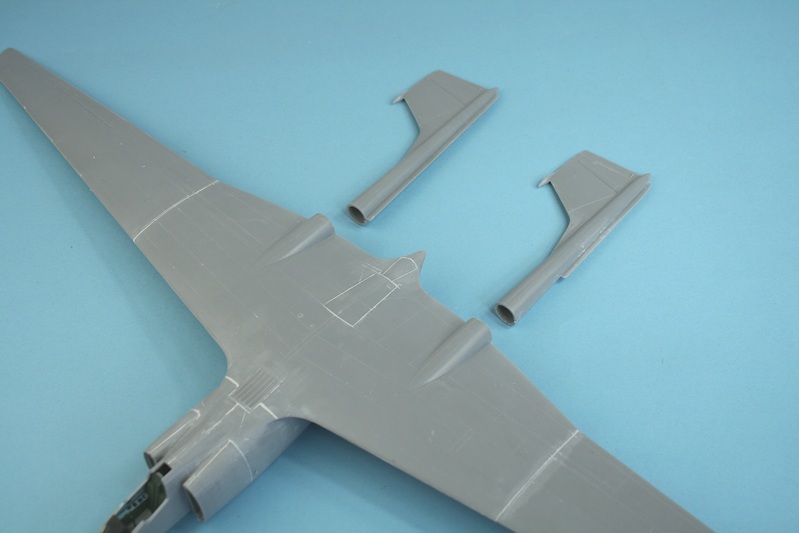
The booms are just a butt join to the wings - some re-inforcement will be needed.
Strengthening plugs from plastic tube.......
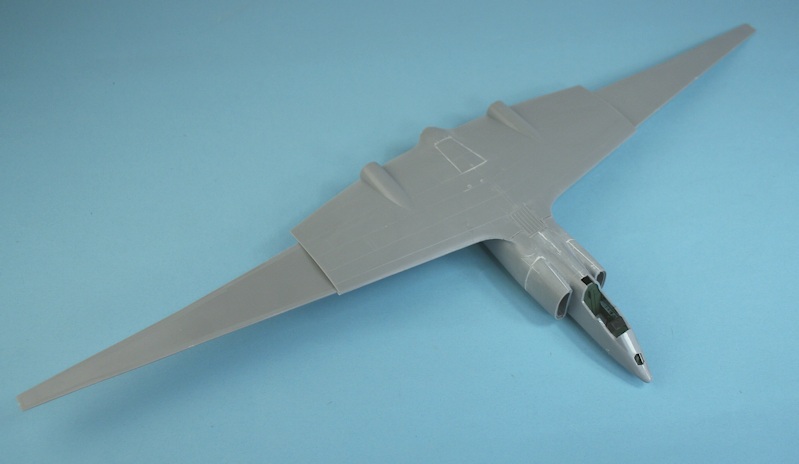
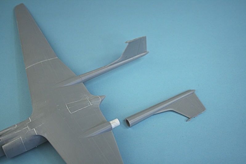
.... and the tail booms are attached - along with the horizontal stabiliser.
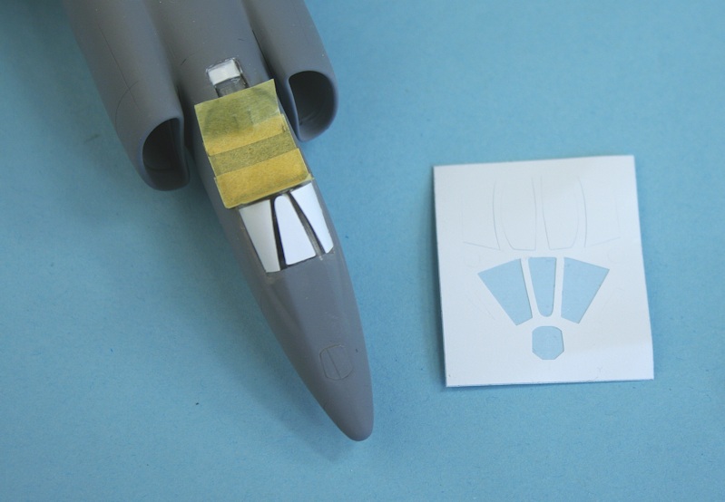
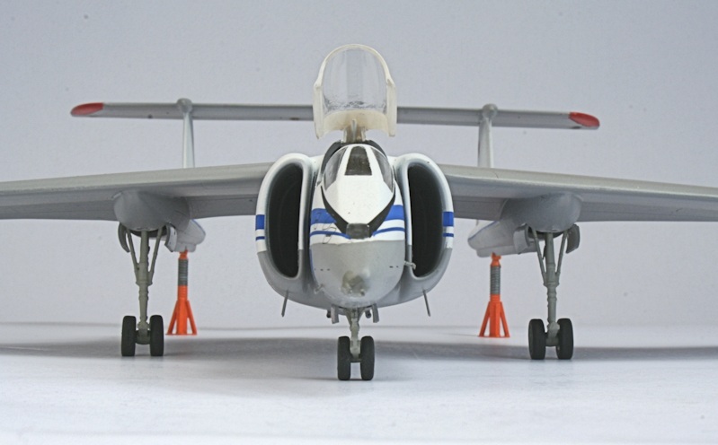
Cockpit sealed off and kit-supplied windscreen masks applied.
White primer applied from a rattle can - to be followed by a top coat of Halfords Appliance White.
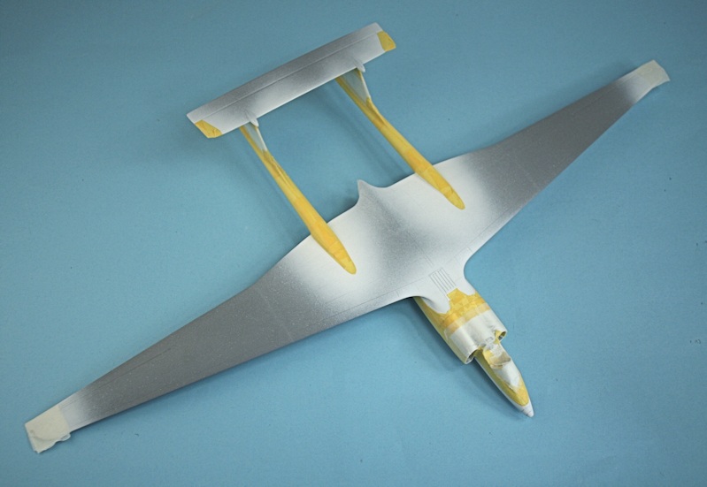
All masked up.
Almost ready for the decals.
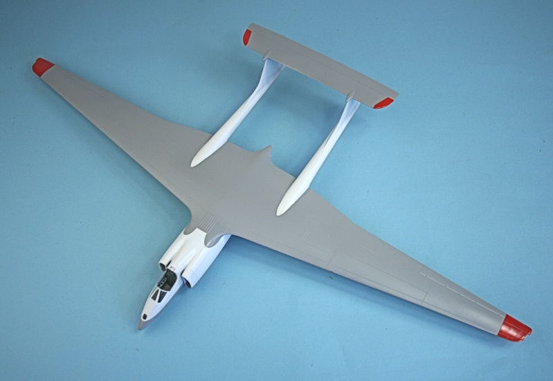
Halfords Appliance White, Halfords Ford Polar Grey and Humbrol red.
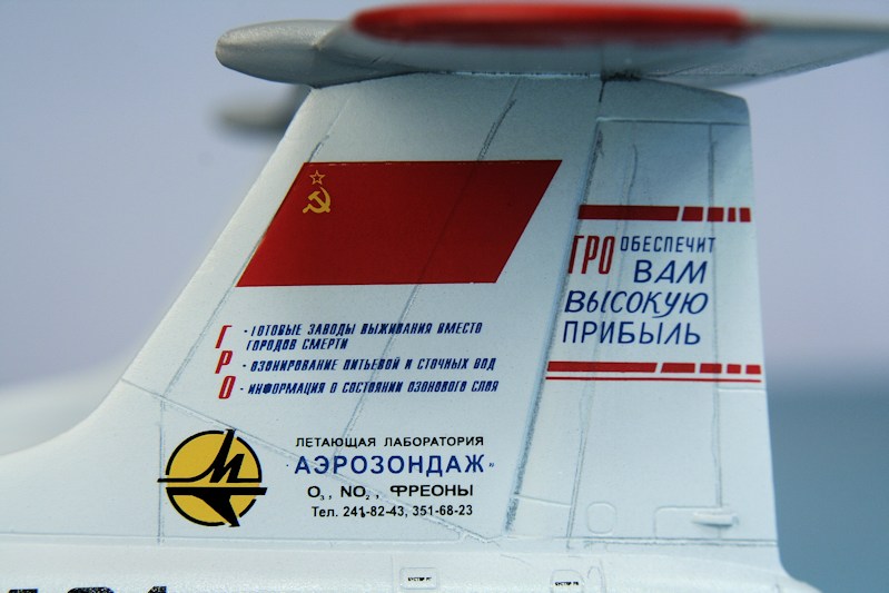
The decals go on beautifully.......
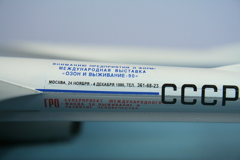
.... and are perfectly readable.
Decals on, sealed with a satin top coat. Despite the inclusion of nose weights...... it's a tailsitter!!
I used more than the recommended 14g - but still not enough.
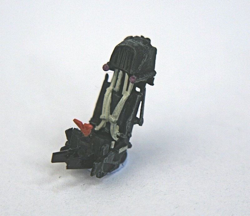
K-36 ejection seat painted......
.... and installed.
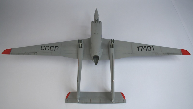
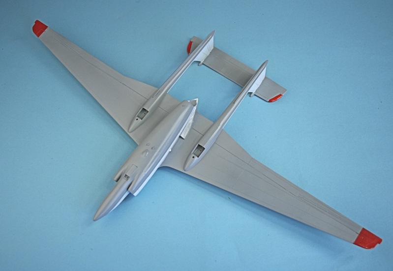
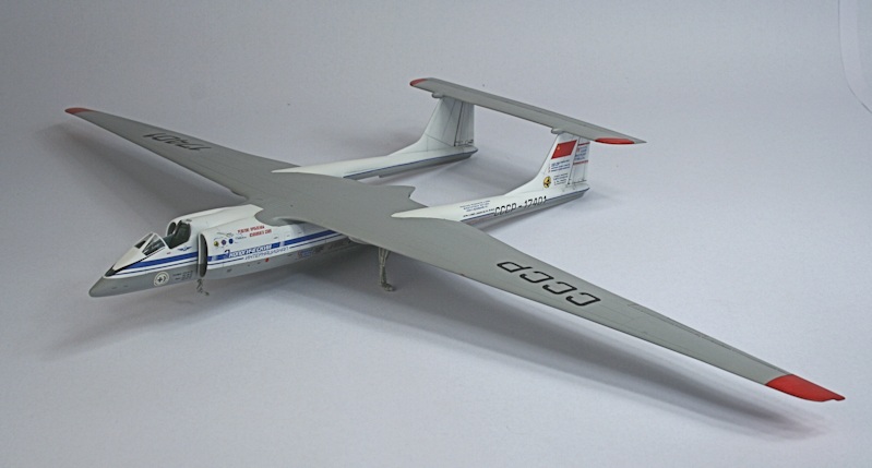
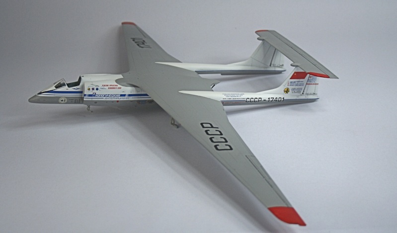
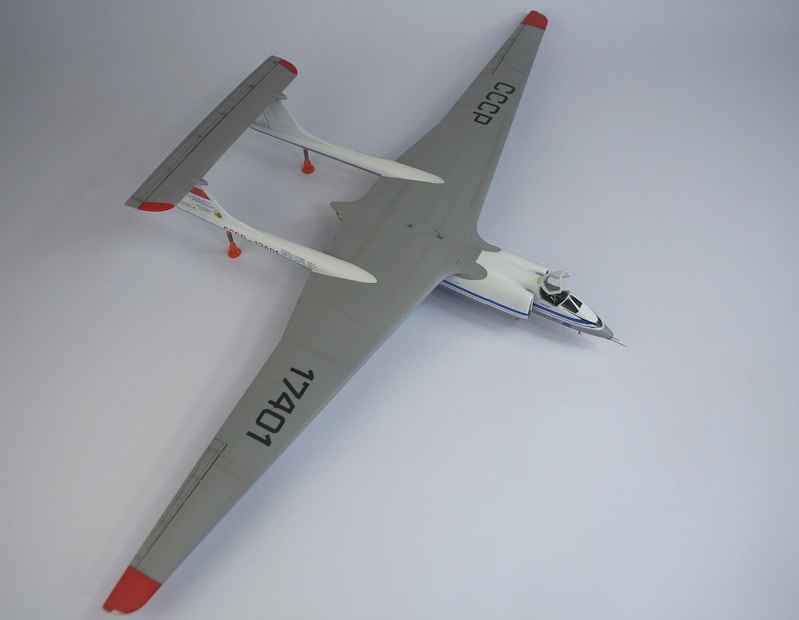
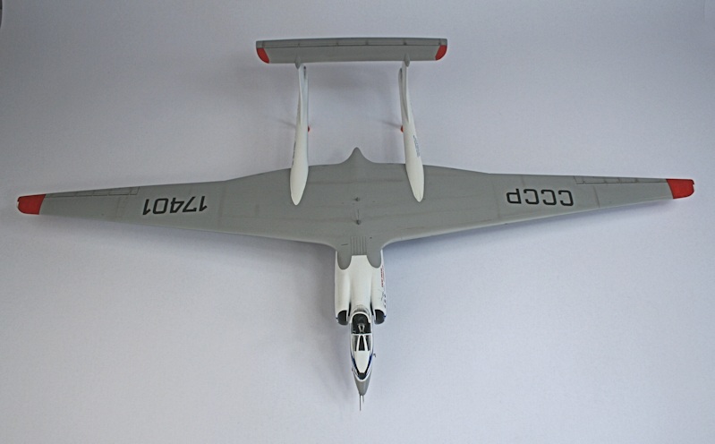
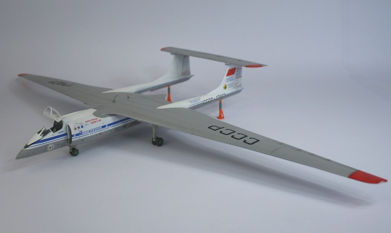
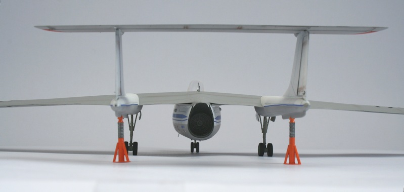
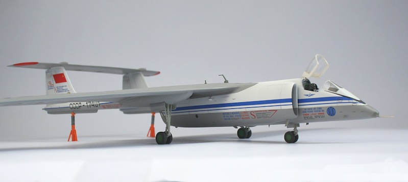
Finished model - underside.
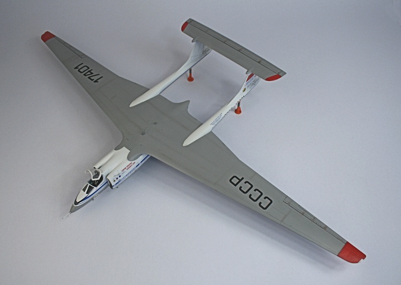
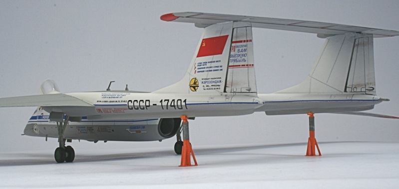
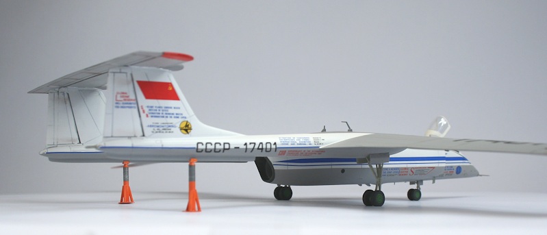
Topside view.
The rear supports are home-made.
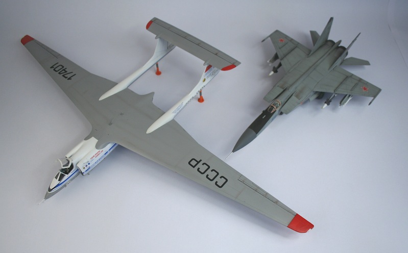
Size comparison - with a MiG-25.
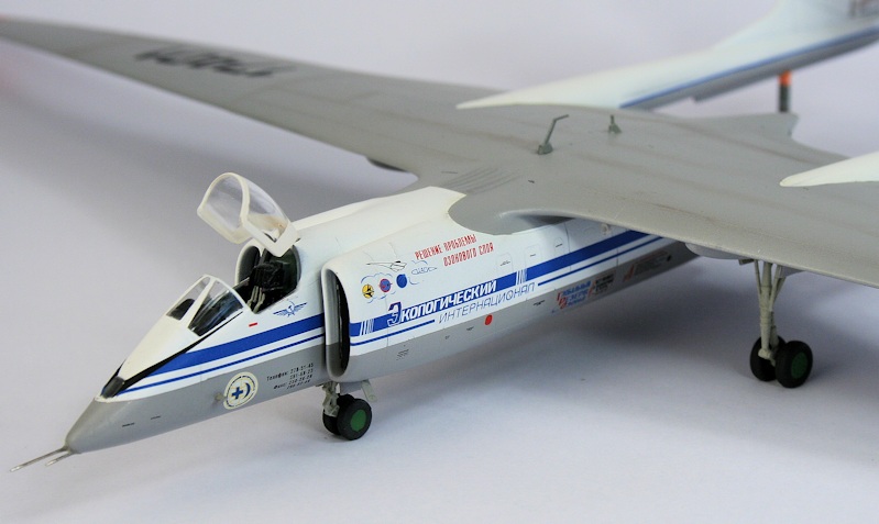
The decals are superb.
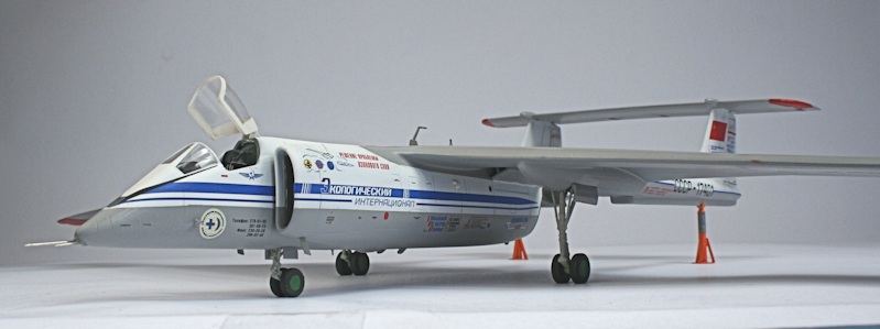
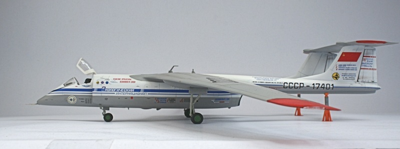
Despite installing the recommended nose weight, it is a tail sitter - hence the scratched supports.
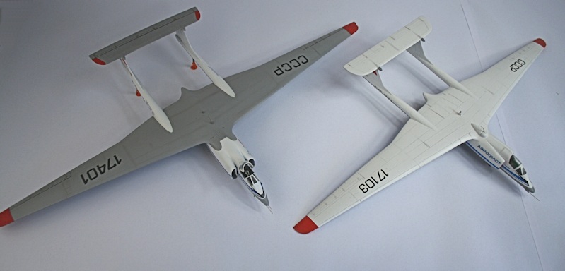
Here's one I made earlier - alongside the Anigrand resin version.
Ken Duffey
August 2016