GRB-36D FICON
The following article was written by me and
published in Scale Models magazine for September 1981.
It is reproduced here with minimal changes
for those who may wish to model the FICON using the re-released Revell/Monogram
B-36 kit....
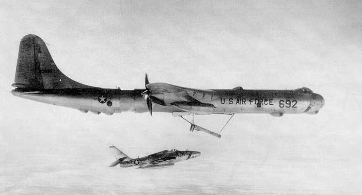
GRB-36D FICON with RF-84K about to engage the later 'production' style
trapeze.
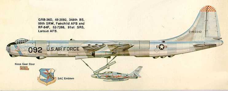
Colour artwork from Squadron/Signal 'B-36 in Action' Note that
the trapeze is of the earlier style.
Background
The original concept behind the USAFs FICON (FIghter
CONveyor)
project was, as its name suggests, to allow the B-36 bomber to carry its
own fighter protection on strategic missions.
A specially designed midget fighter, the McDonnell XF-85, was built
and flown. It was intended that the B-36 would carry three of these parasite
fighters internally but the size of the bomb-bay was a limiting factor
in their design and the resulting aircraft, which was virtually a 3000
lb thrust Westinghouse XJ34-WE-22 Turbojet fitted with tiny 2lft 2in wings
and a cockpit, suffered from stability problems. The prototype XF-85 Goblin
made its maiden flight on August 23 1948 and as the B-36 was then unavailable,
test launches were made from a modified B-29, 44-84111.
On the first attempted hook-up, the pilot of the Goblin found he could
not engage the trapeze beneath the bomber and after several unsuccessful
attempts, during which the cockpit canopy was shattered and the pilots
helmet torn away, the XF-85 was landed on its skid at over 160mph. Subsequent
launches and recoveries were more successful and the concept proved quite
feasible. Three reasons however caused the XF-85 FICON project to be abandoned.
Firstly the loss of the bomber after launching the fighter would also result
in the the loss of the fighter due to its limited range. Secondly with
only 115 gallons of fuel the fighters endurance was strictly limited and
finally, and most importantly, trying to retrieve the fighter in the midst
of a battle when its fuel was low would be extremely hazardous to both
aircraft. Consequently the XF-85 was cancelled at the end of 1948 and the
project shelved.
Despite the failure with the XF-85, Convair was given a contract to
convert a B-36 to carry a single Republic F-84E fighter. Consequently,
RB-36F-1 49-2707 was modified to GRB-36F configuration and made its first
contact on January 9 1952. Further cycles of launch and retrieval followed
and on May 14 1952 a composite flight was made with the F-84E stored in
the bomb-bay during take off and landing.
By mid-February 1953, flying from Eglin AFB, the composite GRB-36F/F-84E
had made 170 launches and recoveries. With the development by Republic
of the swept-wing F-84F, the preproduction YF-84F was assigned to the test
programme and following further successful trials with this aircraft Convair
were given the go-ahead to modify ten RB-36D's :-
44-92090, 44-92092, 44-92094, 49-2687, 49-2692, 49-2694/5/6, 49-2701
and 49-2702 into carriers and Republic were instructed to produce 25 RF-84K
parasites, the emphasis of the programme being switched from fighter escort
to the provision of an extension of the reconnaissance bombers range from
2810 miles to 3990 miles. With the RF-84Ks over-the-target speed of 580
mph the carrier aircraft could standoff at a relatively safe distance from
the target.
The GRB-38Ds served with the 99th Strategic Reconnaissance Wing at Fairchild
AFB, Washington whilst the RF-84Ks were operated by the 91st Strategic
Reconnaissance Squadron, Larson AFB, Washington. The technique employed
was for the aircraft to take off separately and then join up for the mission.
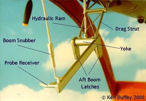
The RF-84K was fitted with a retractable probe in front of the cockpit
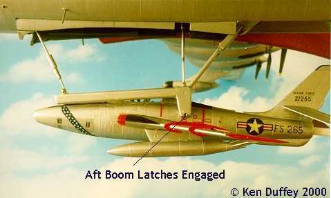
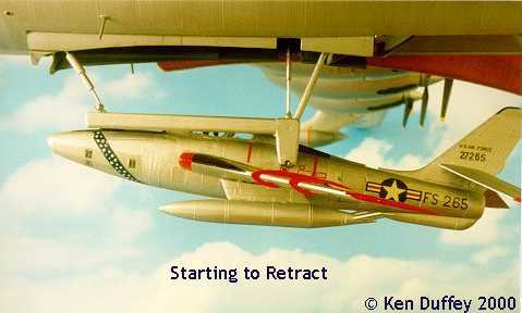
which engaged a probe receiver on the trapeze. The h-shaped cradle was
then lowered to latch onto two retractable pins on either side of the fuselage
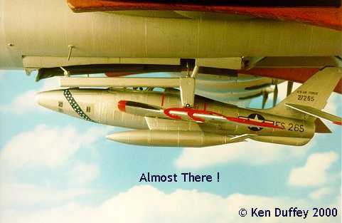
behind the cockpit; the parasite was then drawn up into the bomb-bay where
flush-fitting doors closed around its fuselage.
Once in the bomb-bay the RF-84K pilot could climb out of his cockpit
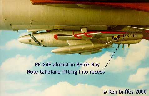
to rest during the flight. Apart from the probe, the only other major modification
to the parasite was a change in incidence of the tailplane in order to
clear the aft fixed fairing. The parasite could be refueled whilst in the
bomb-bay and controls were fitted to it to effect release from the carrier.
Other changes included modification of the camera access doors, revised
cabin temperature controls, the addition of external power and refueling
receptacles and the installation of a ground position indicator.
Modifications to the RB-36D consisted of the replacement of the bomb-bay
doors with plug and clearance doors, installation of the trapeze, provision
of a trapeze operator station in the camera compartment and the fitting
of two independent hydraulic systems for trapeze and door actuation. In
addition, a parasite release system, safety and auxiliary equipment, night
lighting, rendezvous equipment and provision for parasite refueling were
incorporated.
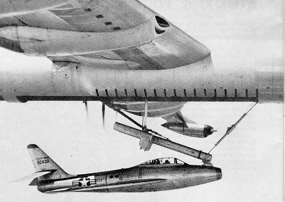
Early trials with YF-84F - Note different style of trapeze.
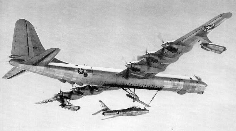
Another view of the same combination.
The Model
With the release of Monograms B-36 kit the modeller can now make four
or five different versions of this aircraft. The simplest, the B-36B, involves
the deletion of the jet pods. By also deleting the armament, the first
version, the B-36A, can be made. The B-36D and RB-36H are both covered
by options in the kit. A more drastic conversion, the jet-engined YB-60,
would involve the construction of new swept wings and tail surfaces together
with jet engine pods. Any modeller who attempted this ambitious conversion
would be left with the wings and tail of the B-36 which, if combined with
a scratchbuilt passenger fuselage, would result in the XC-99 Cargo aircraft!
The GRB-36D, the subject of this article, is slightly easier involving
only minor alteration to the B-36 and an Italeri RF-84F together with a
scratchbuilt trapeze to fit in the bomb-bay.
Stage 1. The Trapeze
In researching this article I discovered that there were two distinct
types of trapeze, the type drawn in the Squadron/Signal book B-36 in Action
and depicted in most of the photographs seen so far, and a smaller, lighter
type drawn for this article. These drawings are based on Convair originals
and the differences have been confirmed by Convair engineers who worked
on the project. Photographic proof of the production GRB-36D/RF-84K combination
is to be found in an excellent book called Thundering Peacemaker by Frederick
A. Johnsen.
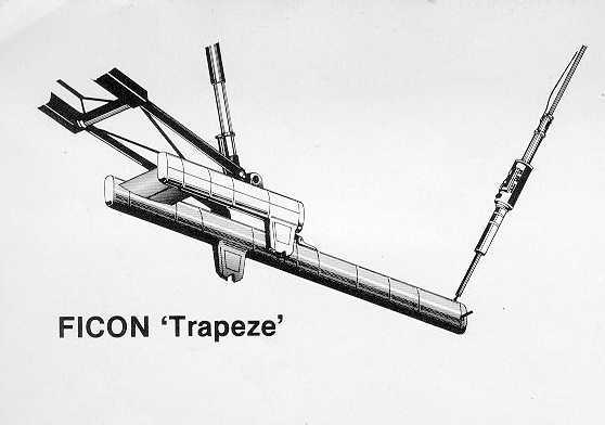
Early style trapeze - compare with my model drawing.
The heart of the trapeze is the Main Jack and this is reproduced on
the model by means of a telescopic aerial of the type found on transistor
radios. The aerial is taken to pieces and the smallest four sections are
cut down to a length of 18mm each. By burring over the upper end of each
section they can be reassembled to make a working jack, 72mm in length
when extended and 18mm long when retracted.
The jack is inserted through a section of plastic rod - which is in
turn cemented to the rear of the main spar (part 17).
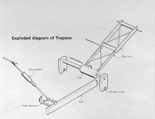
The boom onto which the parasite hooks is made from two laminations
of 60 thou plastic card cut and sanded to shape. The yoke consists of a
17mm long section of 7mm dia. Plastruct rod with a suitable piece of circular
section sprue inserted through the centre joining the two aft boom latches.
This arrangement allows the boom to pivot about the yoke.
The drag strut is in two sections. The upper part, made from 60 thou
plastic card, is joined to the lower section (made from sprue) on Microrod
hinges. The upper pivot consists of a 18mm long section of 3mm dia. Plastruct
rod with a length of metal rod through its centre. This metal rod fits
into holes drilled through two pièces of 60 thou plastic card cemented
into each fuselage half. The boom snubber, made from varying thicknesses
of plastic rod, is attached to the forward end of the boom by a simple
pivot.
To overcome the problem of making a true-to-life telescoping snubber,
the upper end simply slides in and out of a hole cut through the forward
bulkhead. To stop it coming out altogether the upper end is bent over at
right angles. Finally the probe receiver, made from a suitably shaped section
of sprue, is attached to the forward end of the boom.
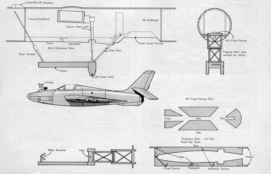
My drawings showing the essential components of the conversion.
My drawing of the 'production' trapeze.
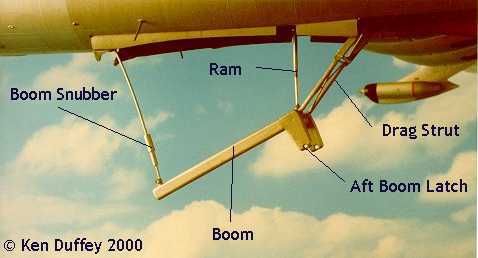
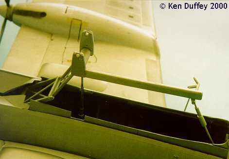
Photo showing the working trapeze on the model.
Close up of the model trapeze.
Stage 2. The GRB-36D
The first job is to extend the bomb-bay aft by sawing along the moulded
lines on each fuselage half back to within 1/2in of the ventral turret
hatch. The rear fuselage bulkhead (Part 78), is carved to circular section
and cemented in place flush with the rear of the extended bomb-bay. Two
pieces of 60 thou plastic card, drilled to take the metal rod from the
upper pivot of the drag strut, are cemented in place in both fuselage halves
as shown in the drawings and the side pieces of the aft fixed fairing are
cemented in place sticking up into the fuselage at an angle of 25 deg.
A hole is drilled in the forward bulkhead on the bottom edge 15mm left
of the centre line to accept the hinge on the port clearance door. Another
hole, 15mm from the lower edge and 10mm left of centre, is drilled and
the boom snubber inserted. The forward bulkhead can now be inserted and
cemented in place.
Cut the two bomb-bay doors (parts 12) to shape as shown in the drawings
(note that the port and starboard doors differ) and cement lengths of plastic
rod at either end to act as hinges. Cement the fixed portions in place
in the bomb-bay. Carry on with the rest of the fuselage as per the kit
instructions but omit the nosewheel (section 5) and the remote gun sights
(parts 82 and 83), except for the rearmost lower pair, and delete the nose
cannons (part 57) as these aircraft were unarmed apart from the tail guns
- being converted from B-36D (lll)'s which had undergone a lightening programme.
(Project Featherweight involved the removal of the guns and their associated
fire-control equipment and the replacement of the drag-producing gunners
blisters with flush-fitting panels.) Small pieces of plastic card should
be cemented over all the unused blister apertures to provide a base for
filler to be added later.
The fuselage halves can now be prepared for joining. Insert the rod
on the forward end of the port clearance door through the hole in the forward
bulkhead and make a hinge for the rear end. Slide the main spar with the
main jack already attached into one half of the fuselage and trap the upper
pivot of the drag strut in the holes provided. With the tail turret in
place the fuselage halves can now be cemented together. When the fuselage
is dry, cement the lower end of the main jack to the yoke with epoxy and
insert the lower end of the snubber into the forward end of the boom. The
other clearance door is fitted next and the front and rear ends of the
aft fixed fairing are cemented in place.
If everything has gone according to plan the trapeze should extend and
retract and pivot about the yoke, the travel being limited by the snubber.
The clearance doors should also operate.
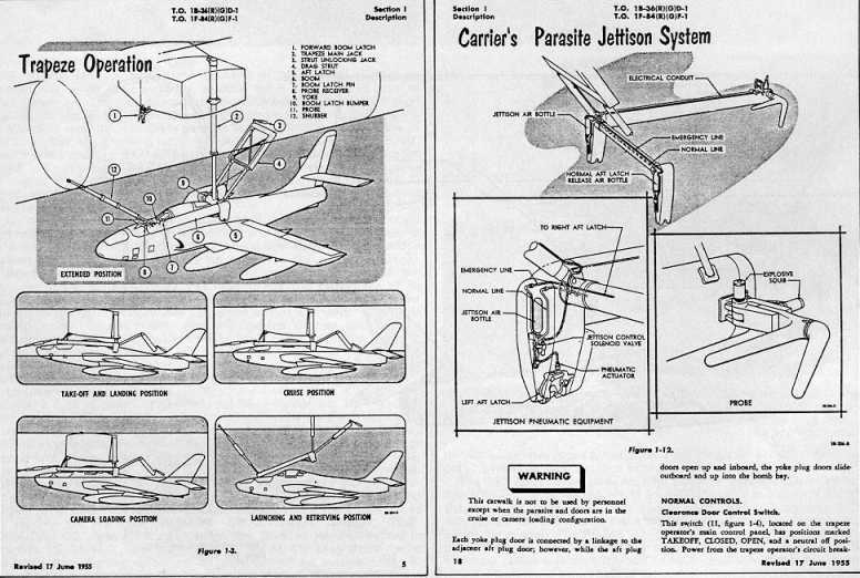
Extract from the USAF operating manual - kindly supplied by General
Dynamics
Stage 3. The RF-84K
This is the simplest of the three stages. Complete the model in accordance
with the kit instructions with its undercarriage retracted but do not cement
the tailplanes (parts 29 and 30) in place yet. A probe, made from scrap
plastic to the shape shown in the drawings, is attached to the upper nose
with its rear end 20mm from the front of the cockpit. A hole is drilled
through the fuselage 42mm from the front of the intake and 5mm up from
the wing root through which a length of hollow rod, the same width as the
fuselage, is inserted. This hollow rod is used to locate the length of
plastic rod which is inserted through one aft boom latch, then the fuselage
and out the other side to the other aft boom latch to suspend the parasite
from the trapeze at the rear end; the forward end being suspended from
the probe receiver. Finally cement the tailplane in place at an angle of
25 deg from the horizontal to allow the rear of the parasite to sit snugly
up against the aft fixed fairing on the bomber.
The final details can now be dealt with. The antenna for the AN/APX-29
rendezvous equipment is made (a Ju-87 mainwheel spat suitably trimmed is
ideal) and attached to the upper fuselage with its front end 10.4cm from
the rear of the cockpit canopy. The blanked-off gunners positions are
filled in and sanded smooth - as is the hole left by the removal of the
nose cannon. The rest of the model is completed in accordance with the
kit instructions for the RB-36D version.
Numerous aerials made from stretched sprue are added to the fuselage.
These aerials are shown to advantage on the back cover of the Squadron/Signal
book which also provides details of the markings carried by a GRB-36D of
the 99th SRW - but note that the trapeze is of the prototype form.
By removing the lugs on the upper part of the nosewheel strut (part
60) and widening the rear section of the nosewheel cavity the undercarriage
will push-fit into place. Monogram have thoughtfully provided two sets
of undercarriage doorsextended and retracted so the model, with a little
modification, can be displayed on its wheels with the parasite in the bomb-bay
or - at its best - hanging in mid-air as if in flight with the trapeze
extended and the RF-84K suspended as though it were about to be launched.
References
Harleyfords US Army and Air Force Fighters 1916-1961
Squadron/Signals B-36 in Action
Thundering Peacemaker by Frederick A. Johnsen, Published by
Bomber Books.
Acknowledgements
I would like to thank Z Joe Thornton of General Dynamics (Convair
Division) for supplying material which was of great help in the
preparation of this article.
Other parasite combinations :-
1. Culver Q-14 drone coupled to the wingtip of a Douglas C-47
2. Two EF-84B fighters coupled to the wingtips of an ETB-39A
bomber (Project MX1016)
3. Two RF-84F fighter/recce a/c attached to the wingtips of a
B-36 (Project Tom-Tom)
4. Two Soviet I-4 fighters attached to the upper wings of a TB-1
bomber - see my model at :- 'Zveno-1'
-
5. Two Soviet I-5 fighters on top of the wings, two I-16 fighters
under the wings plus an I-Z fighter
on a trapeze under the fuselage - 'Zveno-7'
my next project !
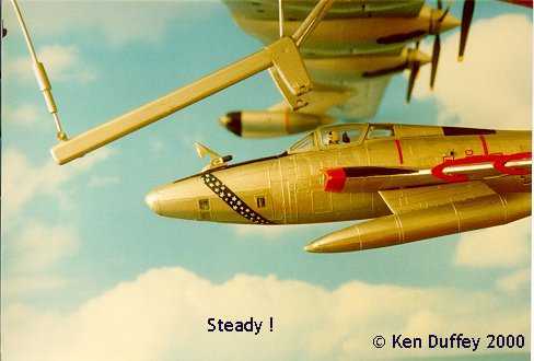
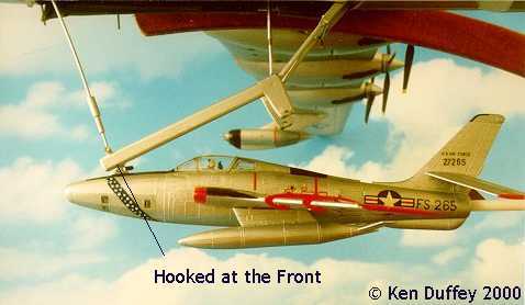
Sequence of photos of my model
RF-84K hooking up to the GRB-36D ..................................

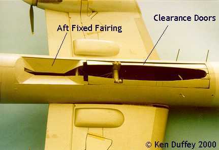
Photos showing the modified bomb bay and trapeze.
Note that my model is incorrect - the forward section of the starboard
clearance door should be fixed - see my drawings.