Trumpeter Tu-160
(NATO Blackjack)
The Trumpeter Kit
Delivered in a stout cardboard box with a superb painting of ‘Illya Mourmets’ wings fully spread on the front, the kit is well packaged in Trumpeters usual style.
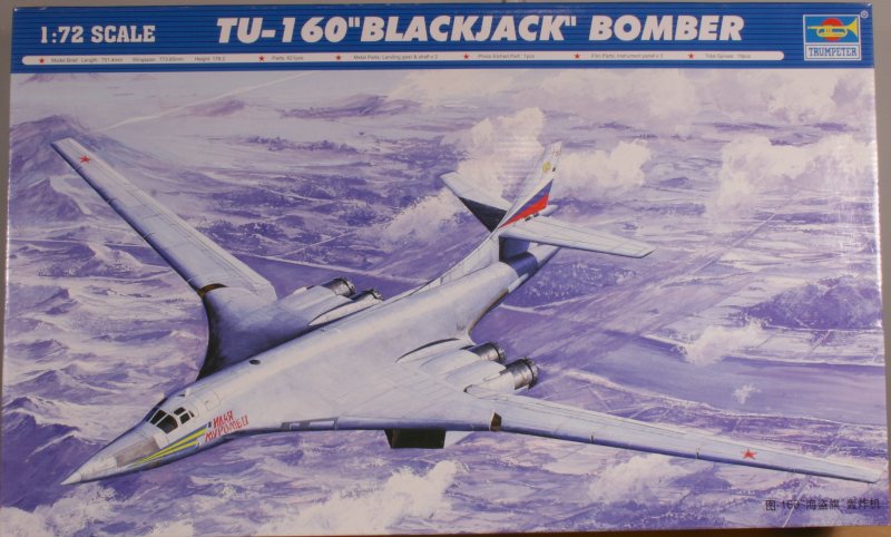
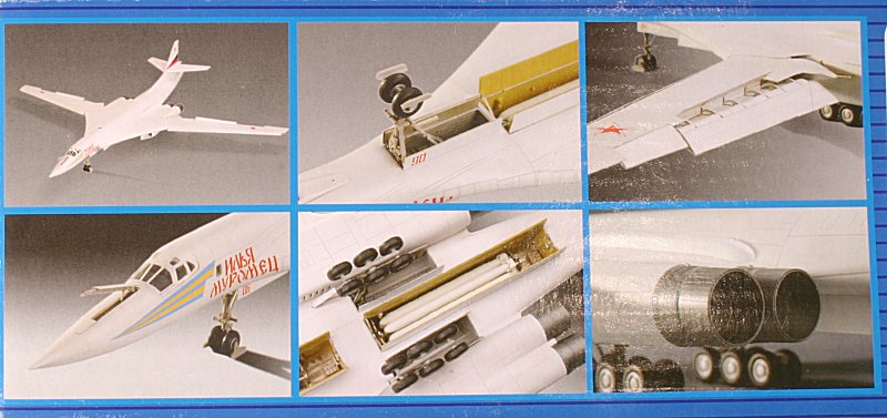
The box top has six photos of the finished model on one side flap – together with the aircraft’s specifications in English & Chinese.
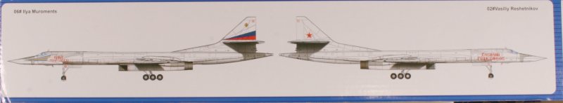
The opposite side flap has a two coloured side profiles - showing a ‘plain Jane’ Vasilyy Reshetnikov and a fully-marked Illya Mouromets.
The plastic components are all individually bagged and there is a separate internal box containing the rubber tires, white-metal undercarriage legs, etched-brass instrument panels and clear sprue containing the canopy, side windows and other clear components – all in separate plastic bags.
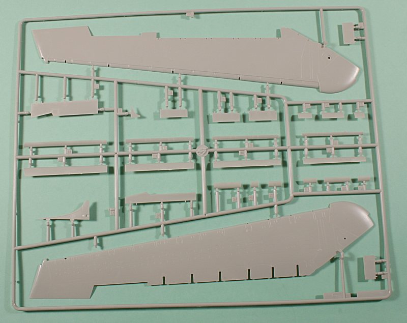
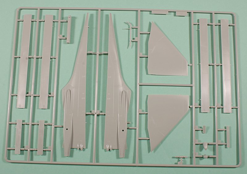
The two largest components – the upper and lower main fuselage mouldings – are loose in the top of the box, but delicate parts – such as the tailcone on the upper fuselage moulding – is protected by plastic wrapping.
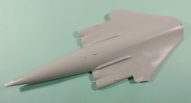
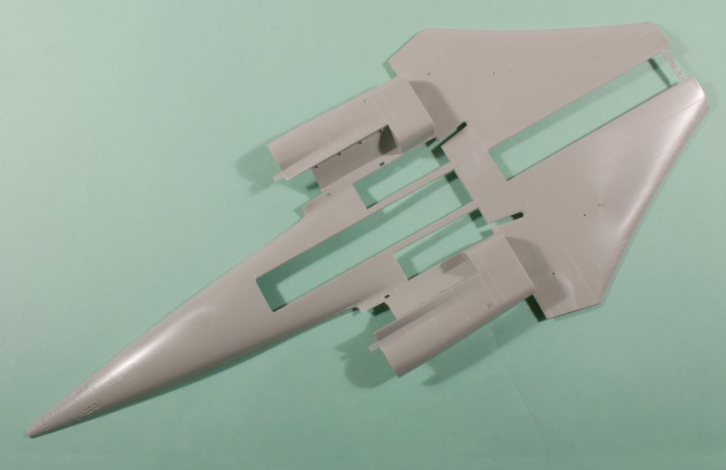
Presumably due to moulding limitations, the forward fuselage is a separate component – in upper and lower halves.
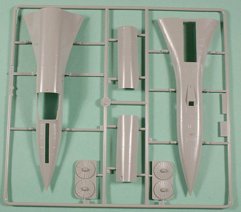
This means that there is a joint line in a very prominent place right across the fuselage behind the cockpit which must be eliminated.
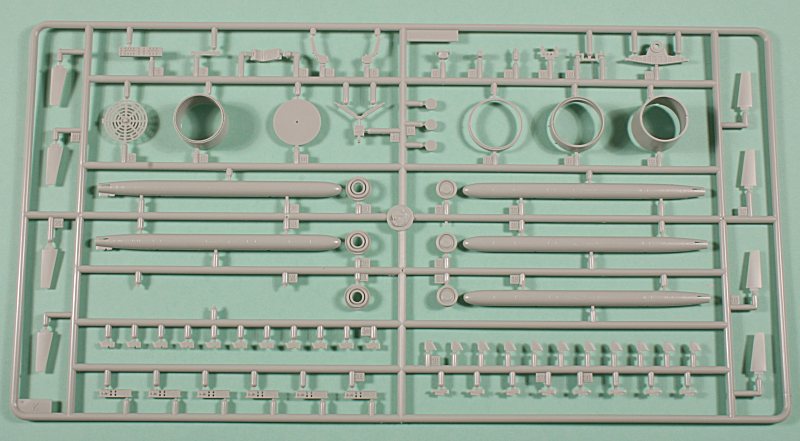
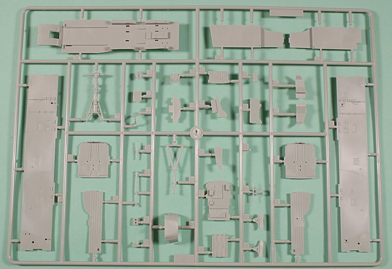
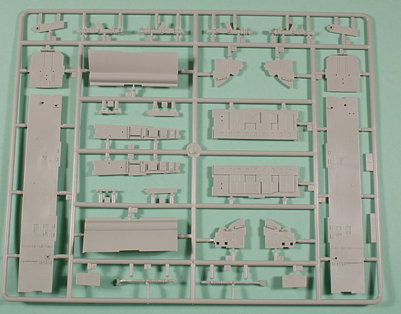
The 609 plastic components are moulded in mid-grey plastic with delicate engraved detail. Approximately 300 of those parts go to make up the twelve Kh-55 and two Kh-55M cruise missiles and their associated MKU-16-5U rotary launchers.
In addition to the grey plastic parts, there is a sprue with 9 clear parts, twelve mainwheel tires plus two nosewheel tires moulded in soft rubber, two maingear legs and two pivoting bogies in white metal, a photo-etched fret containing the Pilot’s and Weapons System Operators (WSO) instrument panels, the K-36 ejection seat firing handles and two parts for the wing root panels.
Finally Trumpeter provides a negative film for the Pilot’s and WSO’s instrument panels.
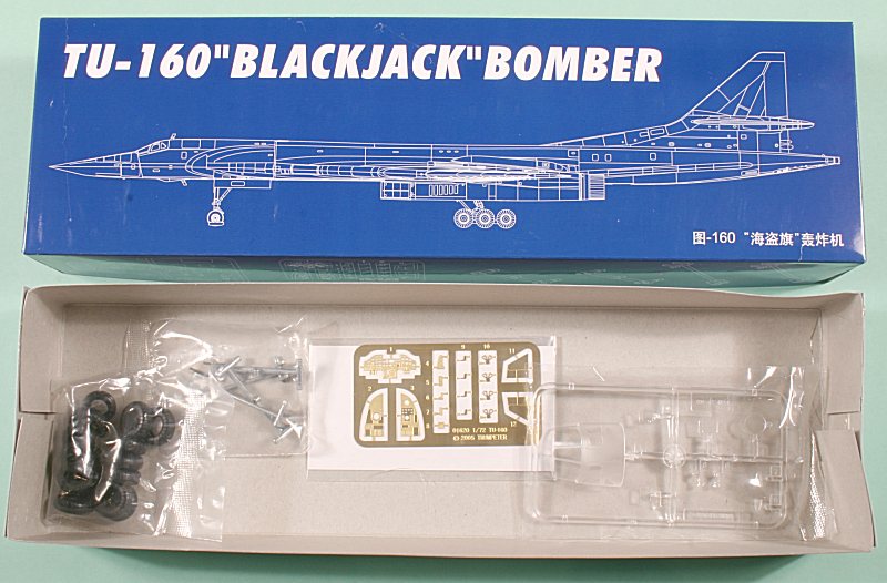
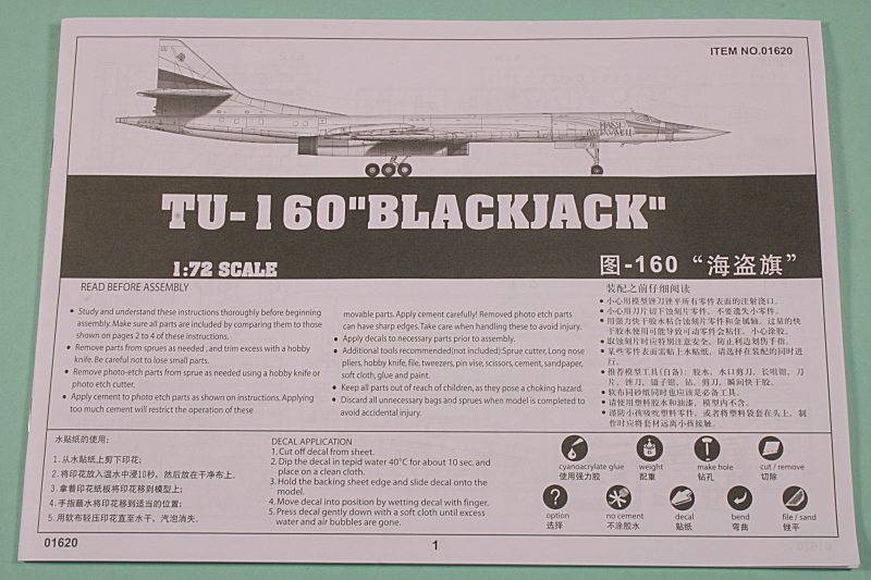
The 20-page instruction ‘booklet’ is well laid out with a logical construction sequence (which I chose to ignore! – well, at least, to modify) and includes some (but not all) paint references matched to Gunze Sangyo/Mr Color paint numbers.
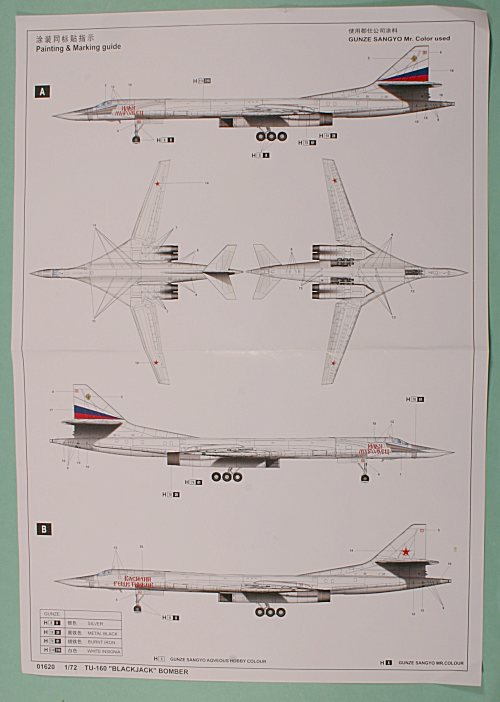
The decal sheet provides markings for just two White Swans – the previously mentioned plain-Jane Vassilyy Reshetnikov with just the name in Gothic-style Cyrillic, the ‘Red 02’ bort numbers and six red stars.
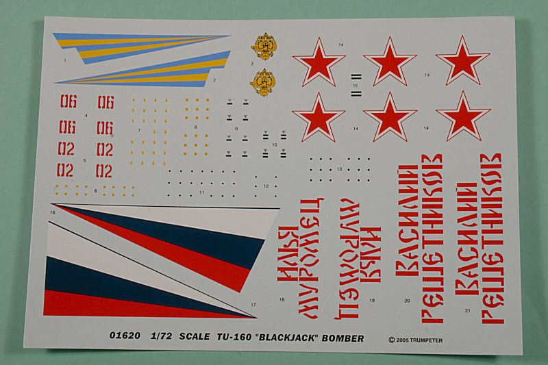
The alternative is bort ‘Red 06’ ‘Illya Mouromets’ – with the ‘full up’ yellow and blue nose chevron and the early-style white/red/blue fin chevron and Imperial double-headed Eagle. - this scheme uses just four of the six red stars.
The decal sheet also contains a limited amount of stencilling and, as supplied is perfectly adequate – but there are better decal sheets on the market, of which more anon.
Construction
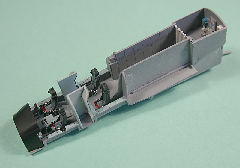
The build begins, naturally enough, with the cockpit. This is very comprehensive, with the four crew places, a long corridor to the rear entrance hatch - it even includes a crew toilet!
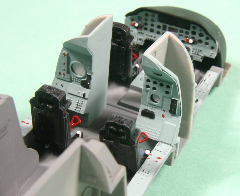
The K-36 ejection seats are reasonably accurate in this scale – not much can be seen anyway, so I chose not to replace them.
Each seat consists of four parts – seat base & back, two side panels and a head box. An etched-brass firing handle completes the assembly.
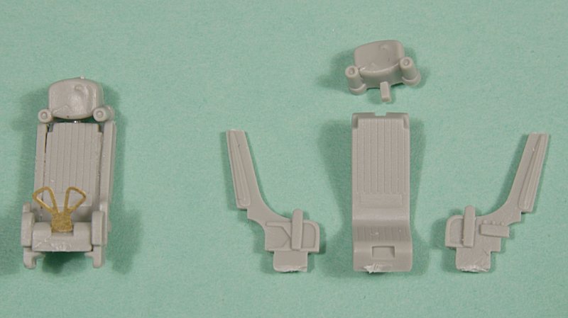
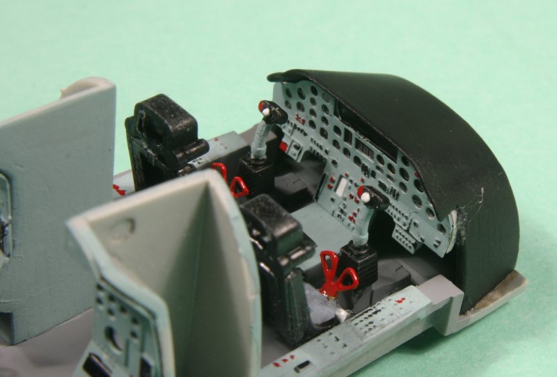
The pilot’s and WSO panels are made up from a plastic part, the photo negative film and the etched-brass panel itself – very effective in representing the real thing.
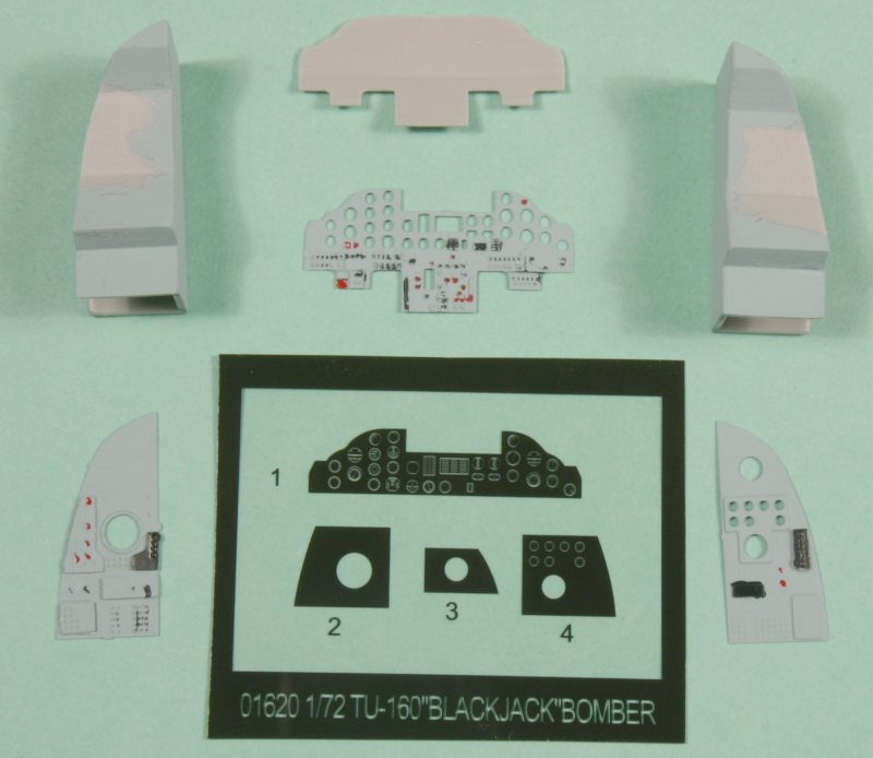
The colours are given as Flat Black & Neutral Gray for the K-36 ejection seats, Blue Gray for the instrument panels, Dark Gull Grey(– why does the spelling change?) for the cockpit floor and Flat Black for the instrument coaming.
This is OK as far as it goes – I used Humbrol Luftwaffe Helblau with a touch of grey added for my panels – I find this mix best matches the pale blue-grey of modern Russian instrument panels.
I had already sprayed the cockpit assembly with Halford’s Grey Plastic Primer – so that took care of the grey floor and ‘corridor’, so all that was left was to add some straps to the seats and paint the firing handles red and the moulded seat adjustment handles white.
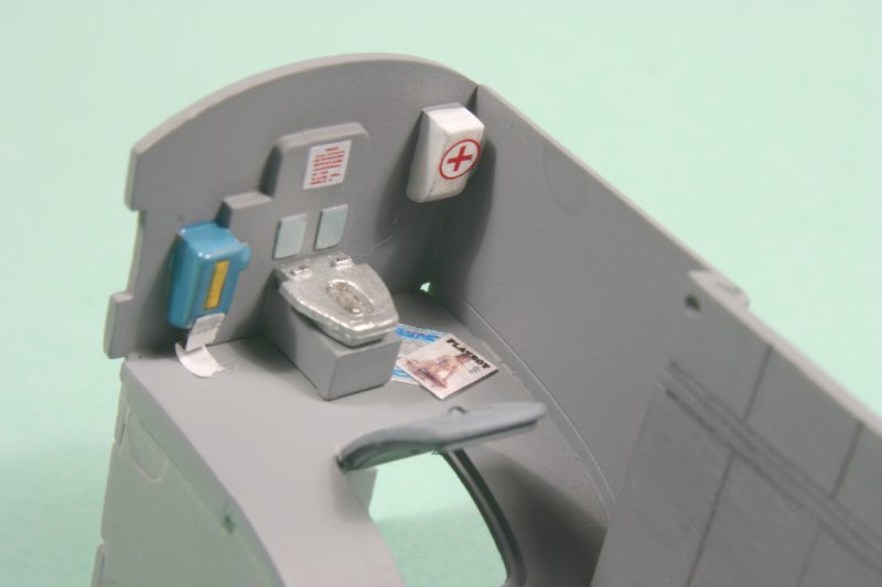
I was intrigued by the crew toilet area. This is located to the rear of the crew station – down a long corridor lined, presumably, with cabinets of instruments.
It consists of a seat pan mounted on the rear bulkhead – just above the access hatch located in the roof of the nosewheel bay.
To save the crews blushes, there is a fabric curtain blanking off the corridor from the toilet, but anyone could come through the hatch!!! I suppose that, like British trains, no-one is supposed to use the toilet when the aircraft is on the ground?
Trumpeter’s instructions note that this toilet should be painted Insignia White – but I figured they wouldn’t have a porcelain toilet – which was confirmed by some Internet correspondence.
I therefore painted it silver – to represent aluminium and just to be a little whimsical, I painted one of the wall-mounted boxes blue to represent a toilet roll holder and the other one white with a Red Cross decal to make a first-aid box.
I searched for and found a couple of magazine covers on the Internet – Playboy and a Russian aviation magazine called ‘Vzlot’ (Takeoff).
These were reduced in size, printed off in colour and placed on the floor beside the toilet seat. If the Russian Tu-160 crews are anything like me, that’s where I do most of my reading!!!
All this interior detailing is just a bit of fun – and none of can be seen anyway, once the parts are installed into the fuselage. The only things visible – and then only by close inspection – are the two front seats and instrument panel.
All the rest is a waste of plastic – and effort making it – but it was just a bit of fun to do.
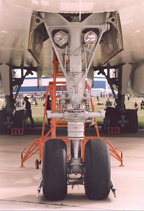
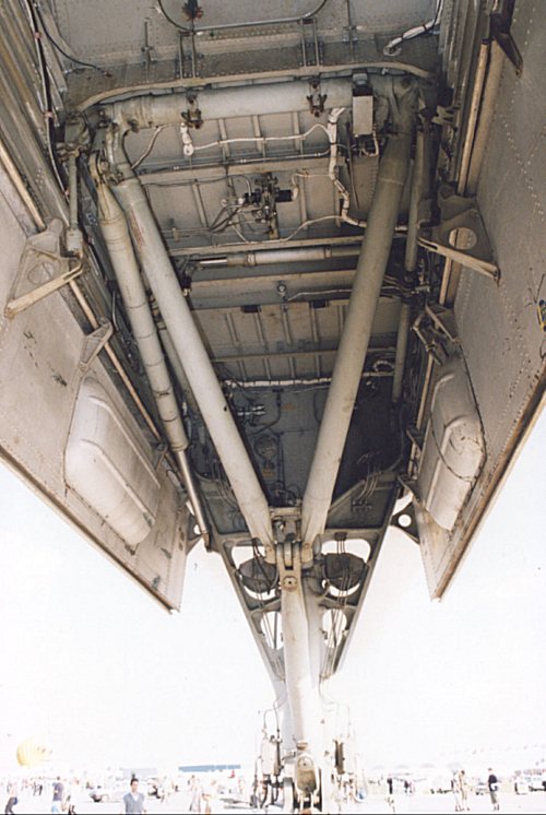
The rear floor of the crew compartment makes up the roof of the nosewheel bay, so sidewalls and front and rear bulkheads are fitted underneath the floor to make the well.
The instruction sheet calls for the nosewheel leg to be added at this stage – in the ‘down’ position.
I realised that this would leave the leg exposed – and I was guaranteed to knock it off during the rest of the build, so I modified the leg to enable it to be placed temporarily it the retracted position. I also wanted the wheels to be offset from the fore-and-aft position to add a little interest.
After cleaning up the leg to remove a bit of flash, I separated the axle from the oleo and the oleo from the leg.
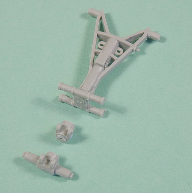
A length of aluminium was inserted into a hole drilled through all three components – with a thicker piece of aluminium tubing threaded on to represent the oleo section.
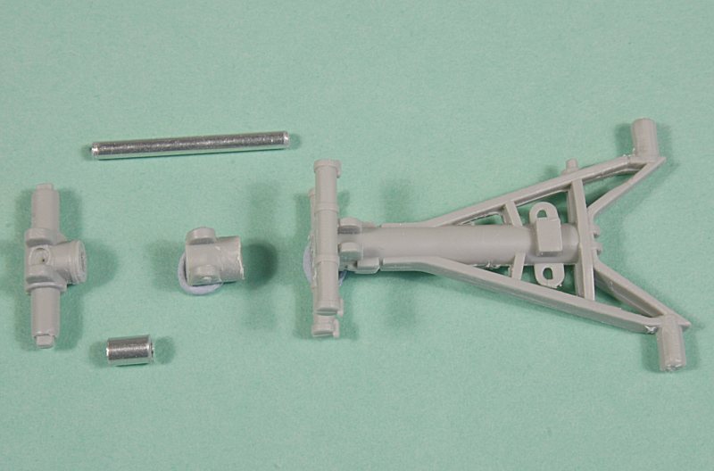
I was thus able to re-assemble the components, but I could now leave off the axle part to be fitted later.
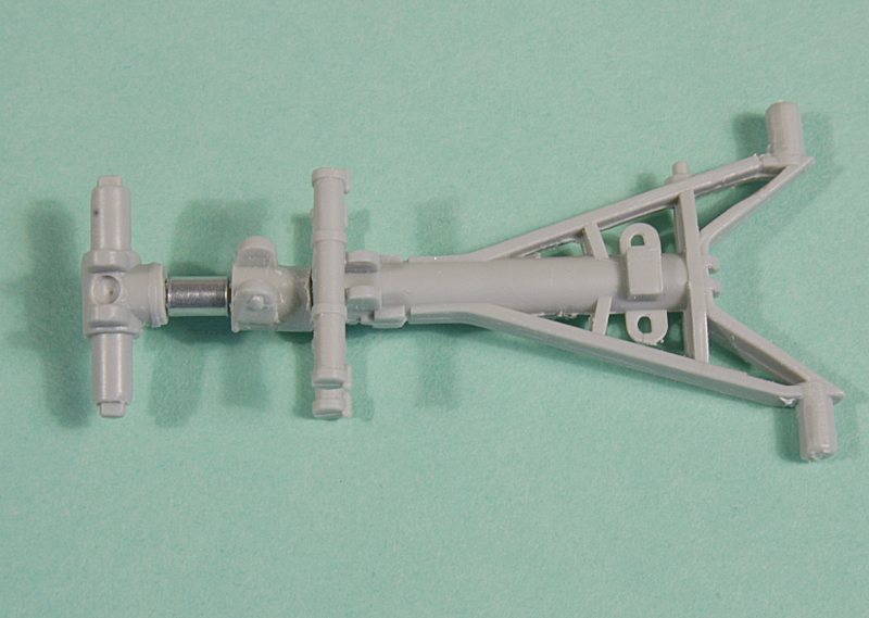
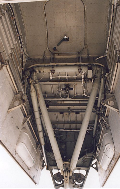
The top pivot on the nosewheel leg is D-shaped and fits into D-shaped holes in the sidewalls – making for a rigid structure.
By reaming out the holes to circular section – and filing off the flat on the upper pivot – the nosewheel leg can be made to rotate and lie flat inside the well.
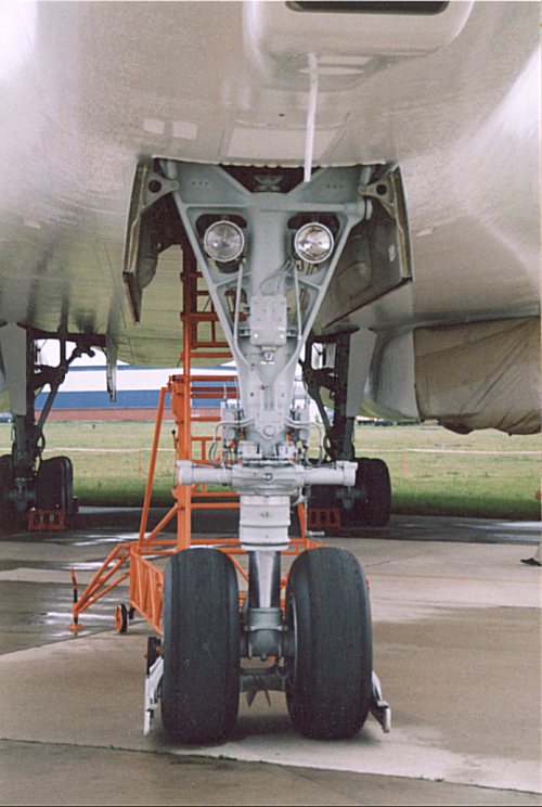
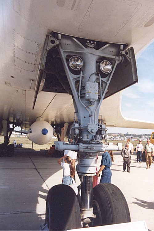
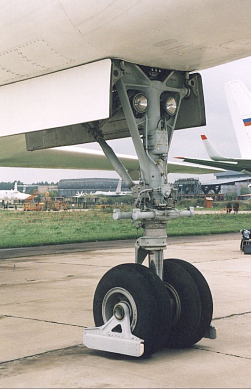
After adding a small junction box, some brake-pipe detail and some electrical cables to the twin landing lights, the assembled nosewheel leg (minus its lower axle) was slipped into place between the nosegear well sidewalls.
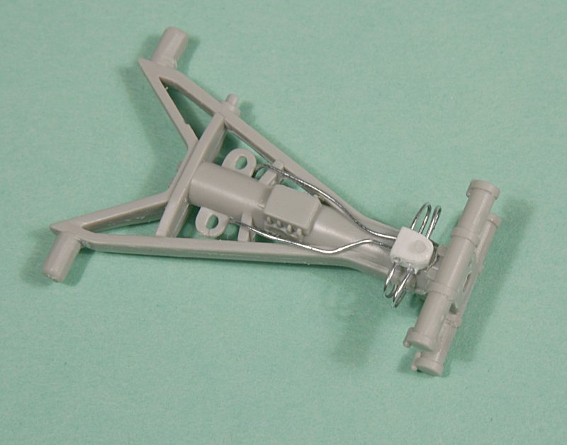
The rear strut (part P24) also pivots, but it is too long to fit inside the well, so the lower strut was removed just below the apex of the A-frame and some brass rod added into a pre-drilled hole in the lower strut.
The nosegear leg – and the rear supporting A-frame – could both now be ‘raised’ into the nosegear well – and would therefore be safely out of the way during the rest of the construction.
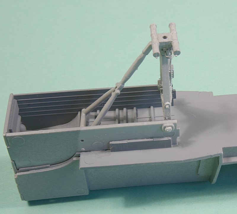
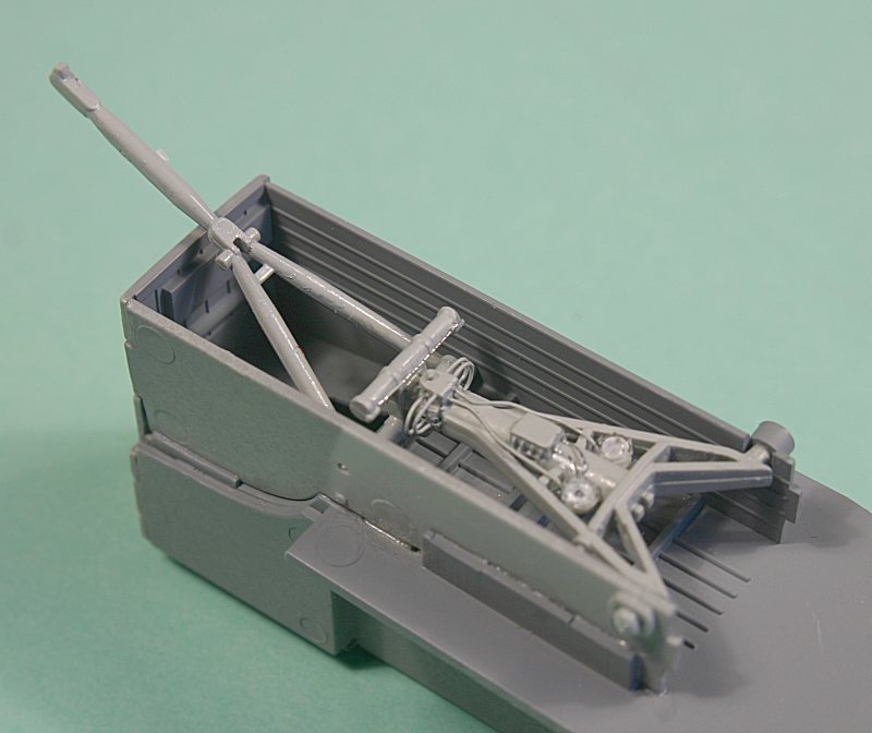
(Note the A-frame is not yet modified in this photo)
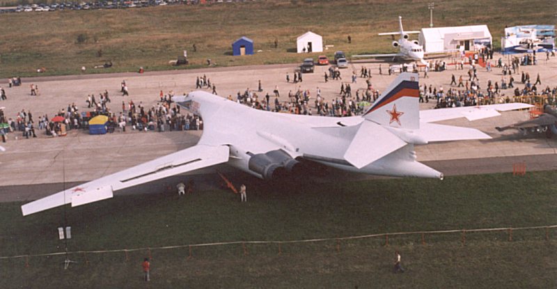
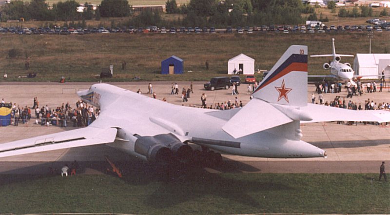
Trumpeter quote Blue Gray for the colour of the nosegear leg – which is perfectly correct for an early Blackjack. The latest one I photographed at Zhukovsky near Moscow was painted pale grey – so I went with that.
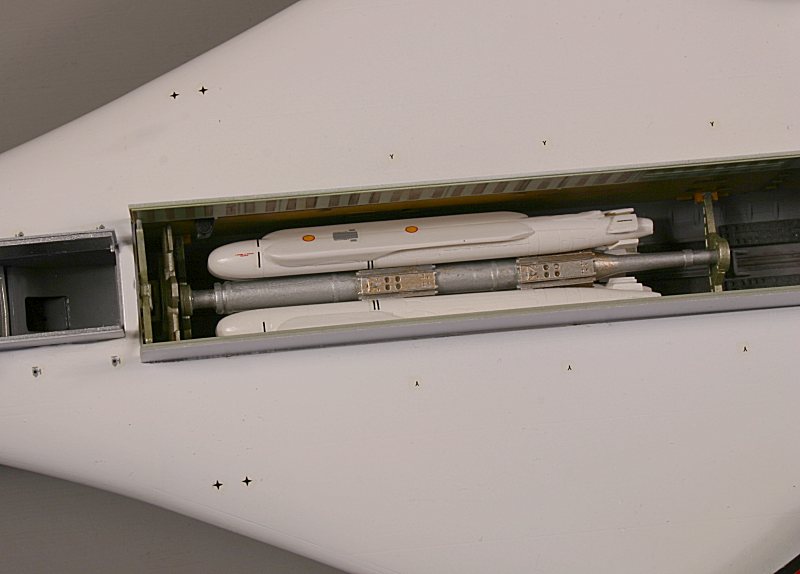
Weapons Bays
The next stage of Trumpeter’s instructions covers the two weapons bays and the cruise missiles – which have to be added prior to the upper and lower fuselage halves being cemented together.
One of the attractions of this kit for me is the inclusion of a full set of twelve Kh-55 cruise missiles on two rotary launchers – one in each bay.
Each MKU-16-5U rotary launcher is made up from a two-part central spindle to which are added twelve mounting brackets – six forward and six aft.
The missiles are each made up from two halves with three folded fins consisting of three parts per fin.
The cruise missiles are fitted to the rotary launcher with wings and ventral turbofan engine retracted – but there is provision to fit the wings in the extended position – although why you would want the wings in the ‘in-flight’ position without the turbofan extended is beyond me.
A more advanced, extended-range cruise missile – the Kh-55M with conformal fuel tanks – is used by the Tu-160 and Trumpeter provide just two examples of this in their kit – complete with extended turbofan.
So, from what Trumpeter provide, you can make twelve Kh-55’s – with or without extended wings & fins plus two Kh-55M’s with or without extended wings or fins – but only with an extended turbofan – a somewhat strange arrangement.
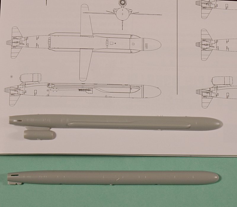
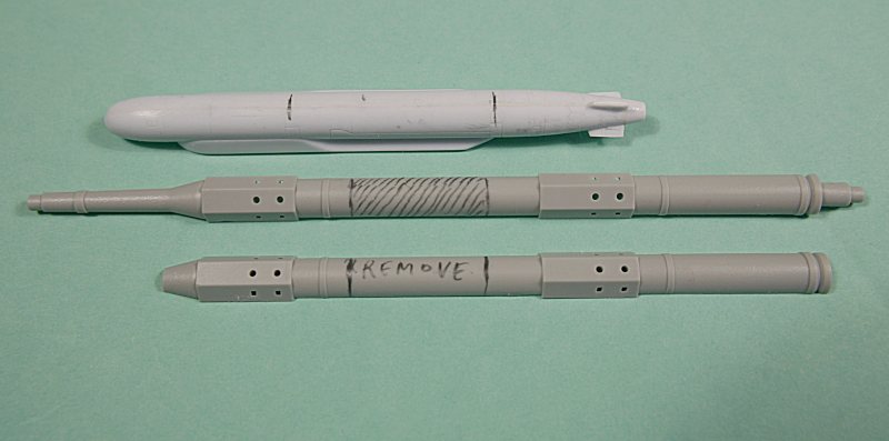
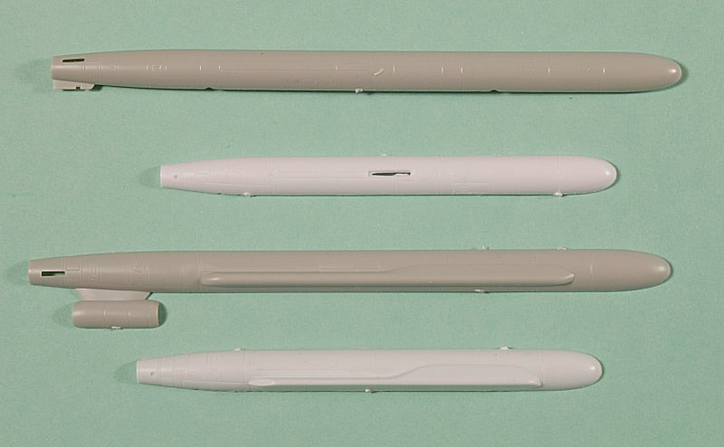
There is however a major error in Trumpeter’s cruise missiles – they are far too long!!!
Trumpeter has assumed – wrongly – that the Kh-55 just fits into the weapons bay, whereas it is really only two-thirds of its length.
The reason for this is that at an early design stage, the Tu-160 weapons bays were configured for the Kh-45 supersonic missile which had a length of 10.8 metres.
Accordingly, the weapons bays were designed to a length of 11.28 metres – which Trumpeter has correctly modelled.
However, the later Kh-55 cruise missiles (and their rotary launchers) are only 8.09 metres long!!
Trumpeter’s 1:72 scale Kh-55 missiles are therefore no less than 20mm (3/4 inch) too long! – so some correcting is called for.
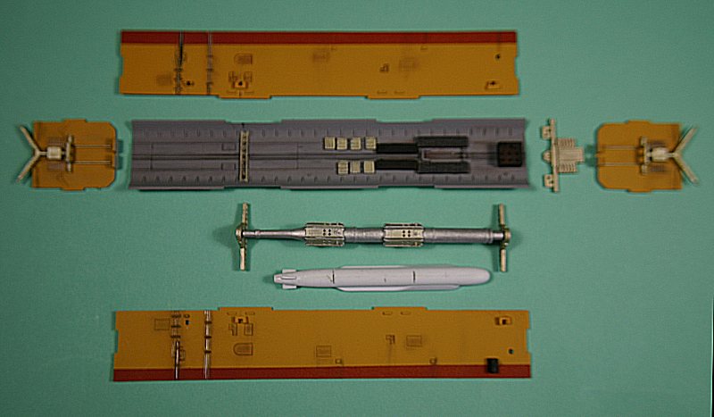
The first job is to shorten the two central spindles of the rotary launchers – parts E18 & E20.
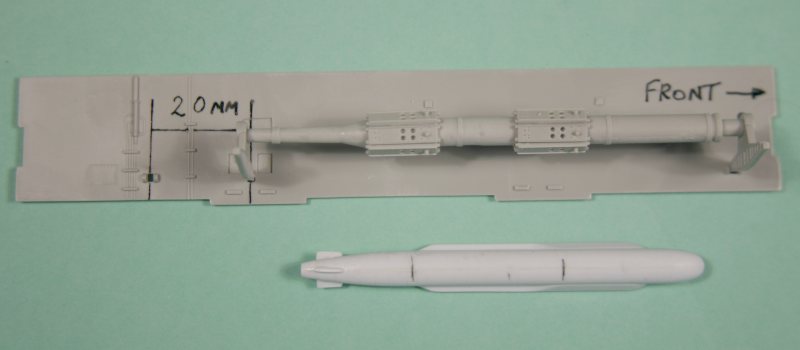
This was done by cutting the spindle in half making the cut at the parallel central section between the two hexagonal mounting brackets. A 20mm section was removed and a length of round-section sprue was cut from one of the sprue ‘trees’ and used to strengthen the joint – before cementing the parts back together.
This gives the correct length for the spindle – but the mounting brackets in the weapons bay sidewalls are now in the wrong place – at least two of them are.
The front mounting bracket in the sidewall can be left alone – but the rear bracket needs to be moved forward by 20mm – at least a new hole needs to be made and the rear hole filled in.
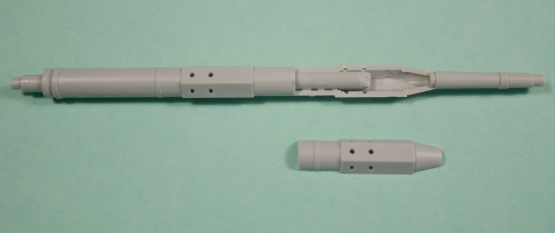
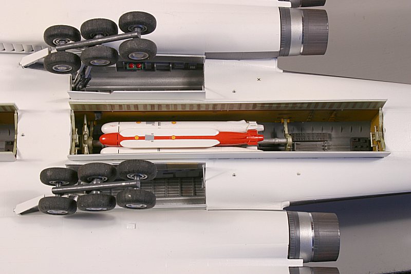
I also decided at this stage that I wanted to get on with construction without having to wait for replacement cruise missiles, so I decided to make the rotary launchers removable.
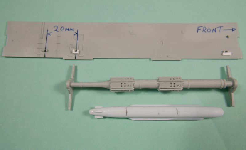
By removing the lugs on either side of the spindle mounting brackets (parts K11) and making U-shaped brackets on the sidewalls of the weapons bays, the spindle and its brackets could just be slotted in place from above - the photographs explain it better than words.
That took care of the MKU-16-5U rotary launcher – but what about the missiles??
I didn’t fancy the task of shortening all twelve missiles (which would have meant making two cuts per missile and then getting them all correctly lined up) – so I chose to use an excellent injection-moulded missile set from the Ukrainian firm of Amodel.
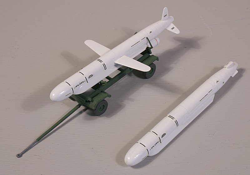
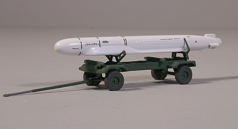
Amodel provide two cruise missiles in their kit – one Kh-55 and one Kh-55M – complete with a transport trolley.
The missiles are accurate, of the correct length and can be built all closed up as they would be inside the weapons bay – or with everything out as they would be in flight. A small stand is provided to show the missile in this in-flight configuration.
But – there are only two missiles per kit – so you would need six boxes for a full set of 6 x Kh-55’s and 6 x Kh-55M’s or TWELVE boxes if you wanted just one missile type inside your Blackjack.
You could of course make resin copies – as long as they are for your own use only……..
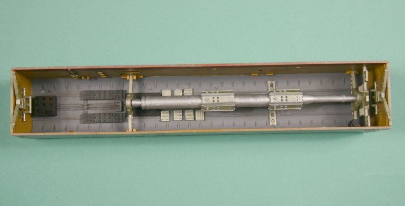
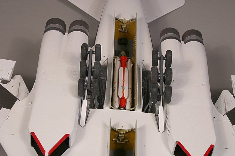
With the ability to fit the launcher and missiles later, I could get on with the construction of the weapons bays themselves.
Trumpeter suggest painting the sidewalls Interior Green and the roof a Gold/Silver mix, but the few published photographs I have seen of the Tu-160 weapons bays show them to have tan coloured sidewalls (that look a bit like plywood!) and a grey roof.
I painted my sidewalls in a zinc-chromate mix with dark tan lower edges and a grey roof.
The ‘fittings’ were as per Trumpeter’s instructions – a Gold/Silver mix with Black and Grey parts.
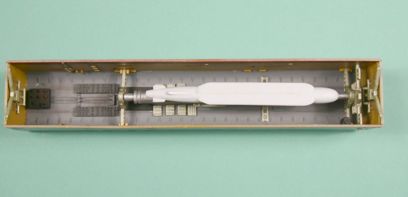
(with Amodel Kh-55 temporarily in place)
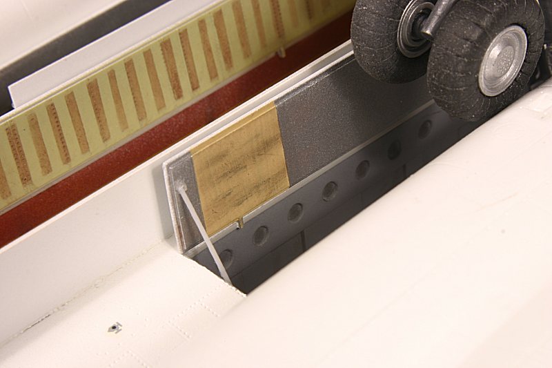
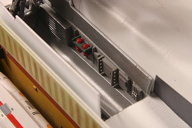
Mainwheel Bays
The mainwheel bays are constructed from a ‘roof’, two sidewalls and two end walls. Detail is accurate according to published photos – with an aluminium roof and end walls plus grey sidewalls.
The two fire extinguisher bottles (K8) should be red with the mounting bracket (E44) a dark green. The larger cylinder (E42 & E43) is pale blue.
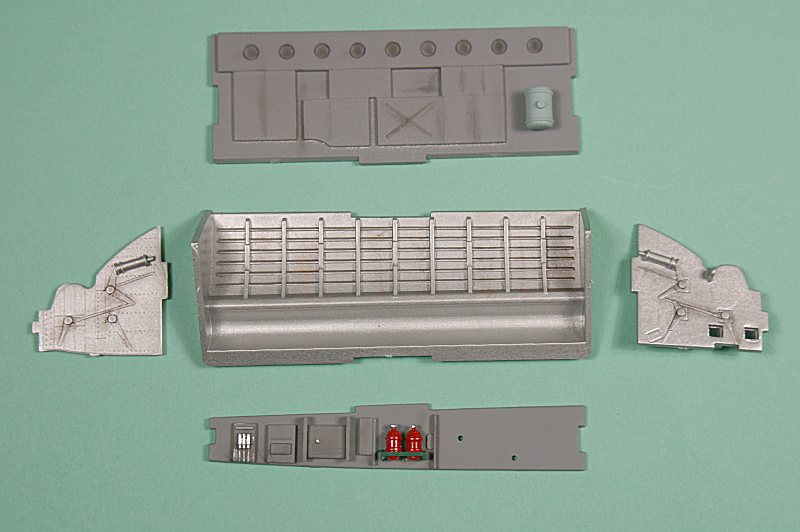
None of these colours are shown in Trumpeters instructions, but they are visible in published photos.
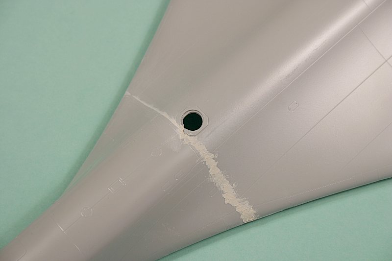
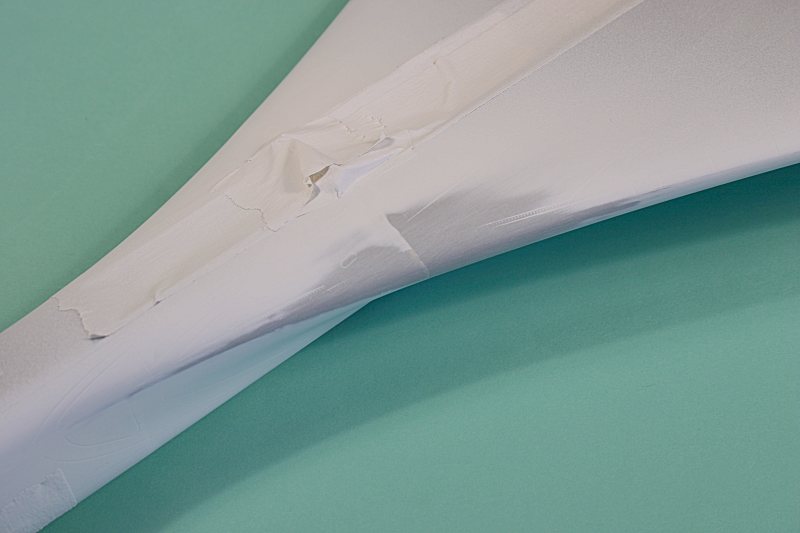
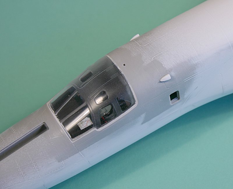
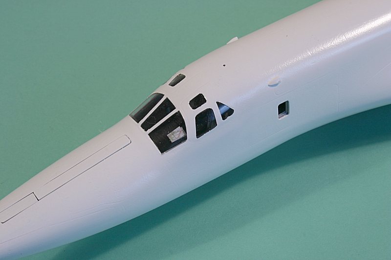
Forward Fuselage
As mentioned earlier, the forward fuselage is in upper and lower halves and is separate from the rear fuselage, resulting in an awkward join.
Before tackling that however, I noticed a curious raised section around the area of the WSO’s side windows. I’m not sure what this is for – maybe Trumpeter had to modify the mould for some reason??
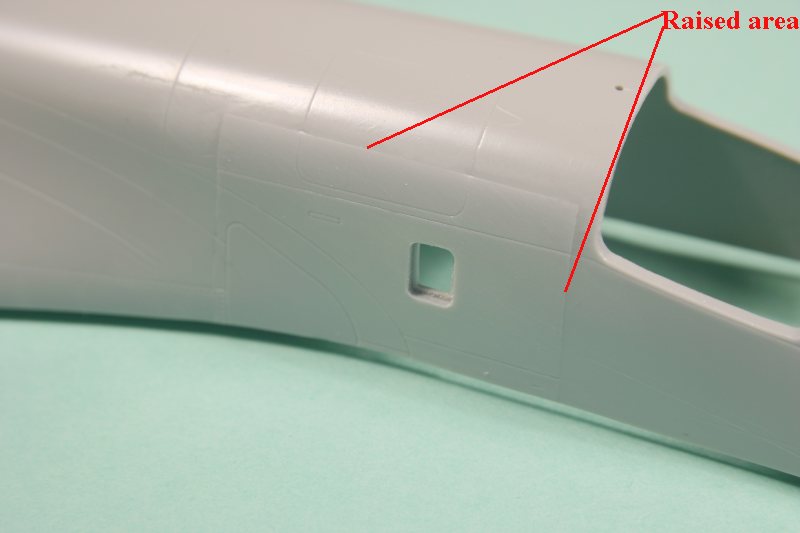
Anyway, it needs to be removed by gentle sanding and restoration of the panel detail.
Trumpeter’s instructions show the forward lower fuselage being cemented to the rear lower fuselage – together with the weapons bays, mainwheel wells, front cabin assembly – all in the one drawing.
I modified the sequence slightly – by first mating up the front and rear lower fuselage halves on a flat surface and cementing them together, trying to get as close a joint as possible.
I also strengthened the joint by adding strips of scrap plastic across the joint on the inside.
There are lots of apertures in the lower fuselage moulding – for the weapons and undercarriage bays, so the structure is quite flexible.
There is also a minimal amount of mating surface area between the box structures of the completed weapons bays and the lower fuselage, so after cementing them in place they joint was strengthened by adding strips of L-section plastic.
Once the main wheel bays were added and the forward cabin cemented in place, the whole assembly takes on a reasonable amount of rigidity – although there is still not a lot of plastic between the front and rear weapons bays.
Swing those Wings
Trumpeter make provision for the wings to sweep, but due to the intrusion of the two weapons bays into the centre fuselage, there is no mechanism to make them sweep in unison.
(Did you know that the Tu-160 has the largest moving surface area of any aircraft – beating the folding wingtips of the XB-70 Valkyrie into second place).
Unlike kits of the Backfire or Tornado – where there is some sort of circular saw-tooth arrangement or a cross-linkage – the wings on Trumpeter’s Blackjack sweep backwards and forwards individually – and the whole arrangement is a bit sloppy anyway.
What Trumpeter provide is a box-like structure that fits into a pivot in the wing root. It has a small raised ‘tooth’ that engages into a couple of slots moulded into the inside wing lower surface.
This is then supposed to ‘click’ at each wing sweep angle – fully forward (20deg), intermediate (35deg) and fully swept (65deg).
The whole arrangement is a bit unsatisfactory – and as I only wanted to display my model with wings fully forward with everything out, I decided to make my own wing fitment.
I also reasoned that with the wings cemented in the fully forward position, the model was going to take up an inordinate amount of room when fitted into a box for transport to model shows – so detachable wings would be nice.
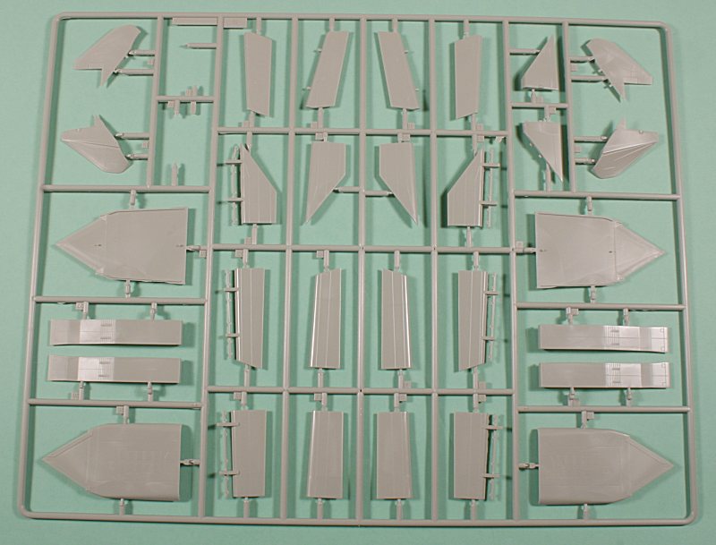
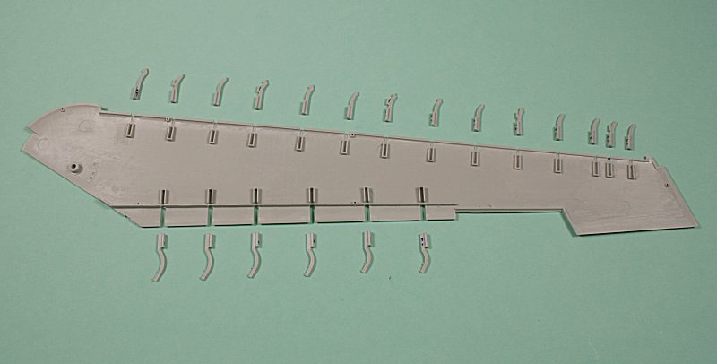
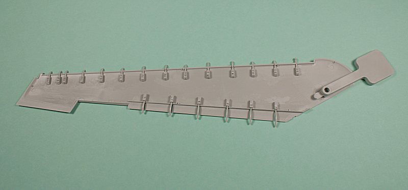
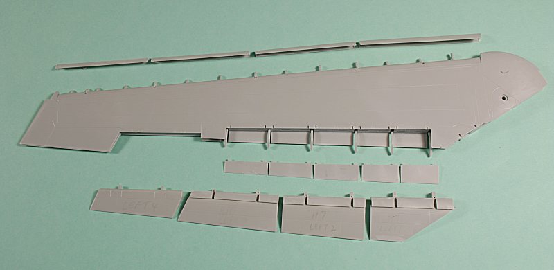
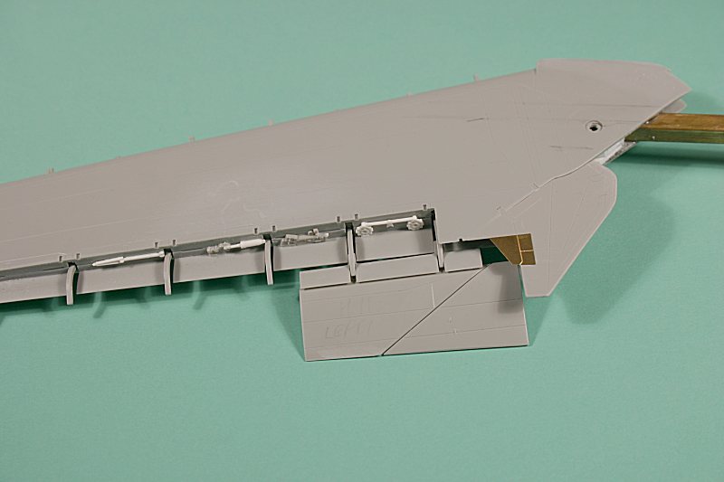
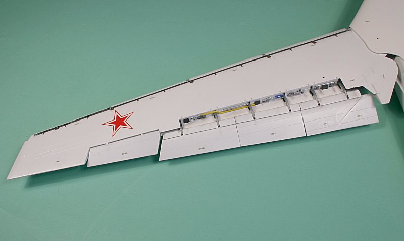
The wings were assembled – upper and lower halves – complete with no less than six flap brackets on the trailing edge and fourteen slat brackets on the leading edge.
I left off the slats and flaps at this stage – but I did fit the wing sweep ‘box’ (part E55) – because I hadn’t at this stage decided on how the wings would be fitted
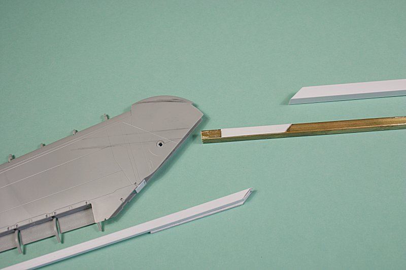
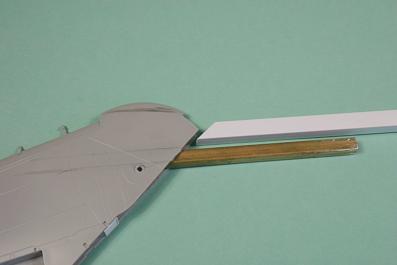
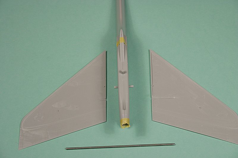
After toying with various ideas and following some internet correspondence, I settled on the idea of a wing spar fitting into a slot inside the fuselage.
After purchasing some square-section brass and plastic and a fair amount of trial and error, I ended up with a short length of square section brass that fitted into a corresponding length of square section plastic.
I had to butcher the already-assembled wings to remove the wing sweep boxes – and I was then able to superglue the square-sectioned brass inside the wing – the length being limited by the angle at which it had to be mounted.
A thinner length of square section plastic was cemented further inside the wing to act as a strengthening spar.
All of these parts should have been added before the wings halves were joined – but I never was a forward-planner – all this detachable wing stuff was done empirically as I went along.
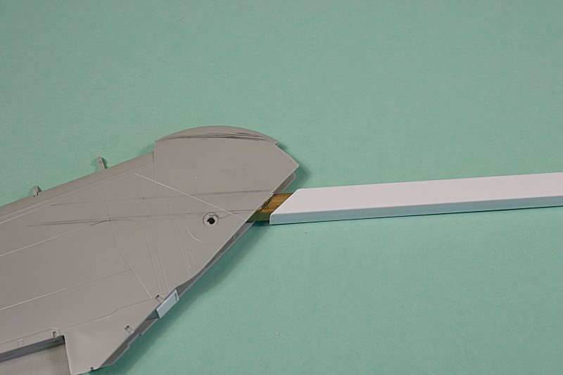
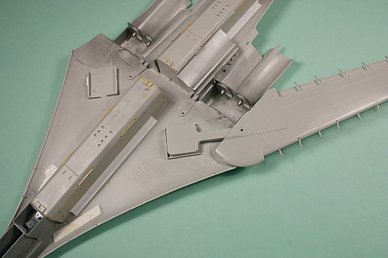
Because the wings are fully forward – and have to be slid into place at right-angles to the longitudinal axis, I had also to remove a section of plastic from the wing root leading edge – part of the ‘knuckle’ that fits inside the wing root leading edge.
I also removed plastic from the top and bottom of the wing root ‘knuckle’ – because the slot into which it now slides is narrower than the inside of the wing root itself.
All of this need not be done – if you want a sweeping wing or are happy to cement them rigidly in place. But I wanted removable wings that were only ever going to be displayed in the fully forward position.
The square section plastic – into which the wing spars slide – was cemented into place inside the lower fuselage between the weapons bay ‘boxes’ and once I was happy that the arrangement worked, it was time to cement the fuselage halves together.
Before doing that, I cemented the upper forward fuselage to the upper rear fuselage – again trying to get as good a join as I could.
There is a long joint line between the upper and lower fuselage halves – and not much surface area to take the cement.
Add to that the fact that the fuselage is still slightly flexible – particularly along the edge of the fixed wing/body area just ahead of the swing wings.
I used thin liquid superglue along this joint – and it still popped open later on. The same thing happened along the rear fuselage – in the area of the raised fuel tank conduits – they had both to be re-glued following some vigorous handling.
You gave been warned – glue them well!
Despite all my best efforts to eliminate the joint line between front and rear fuselage halves, it was still visible – especially after a applying a coat of primer to highlight just such a problems.
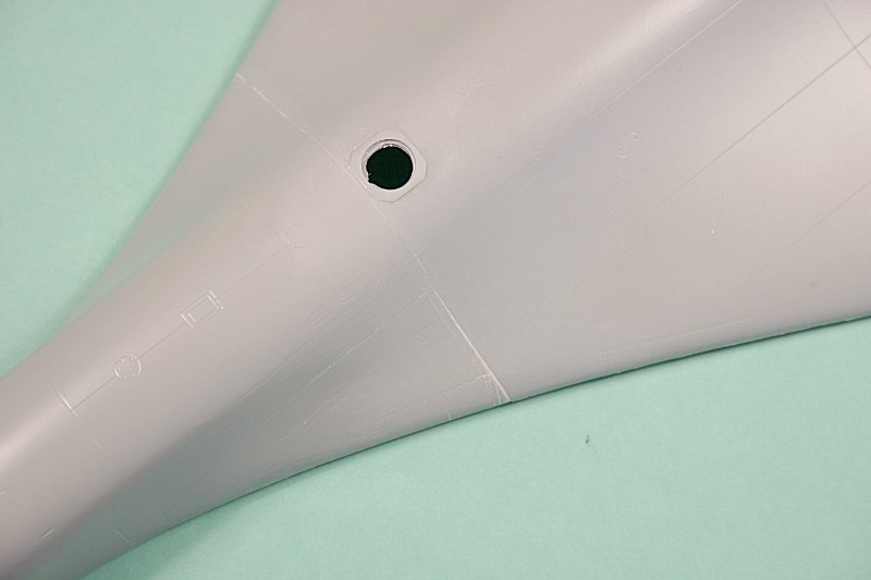
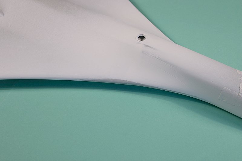
So it was out with the sanding block until all traces of the joint had disappeared.
It did mean that the panel detail had to be re-scribed – no easy task when the panel lines are compound curves right on the wing/body blend – but the effort was worth it.
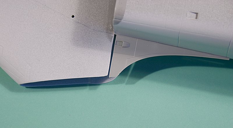
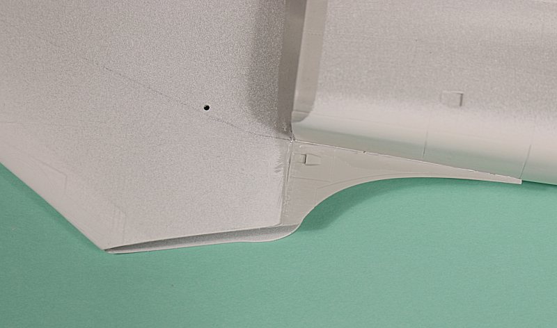
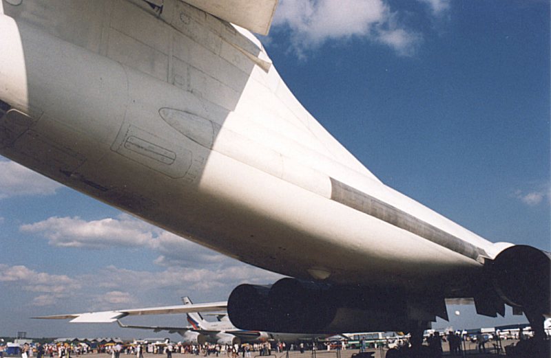
The lower fairings between the fixed wing glove and the engine nacelles were added next (parts F26 & G26).
A dry-fit revealed a gap between the front of the fairing and the rear of the wing root – easily fixed by removing a sliver of plastic from the locating tabs which served to move the fairing further forward.
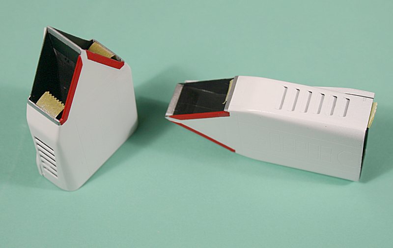
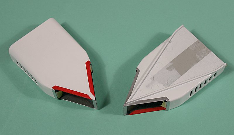
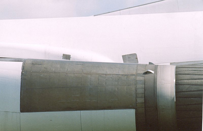
Engine Intakes
I decided to fit the engine intakes out of sequence – because they need to be assembled and painted before being fitted in place.
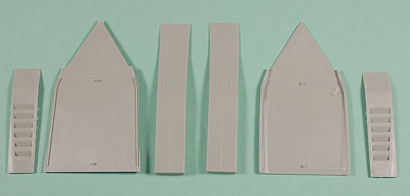
Each separate intake consists of a top and bottom section with a two-part central divider and two side walls with six auxiliary blow-in doors moulded in the open (engine running) position.
The insides of the intakes on the real thing are made of a matt black Radar Absorbent Material (RAM) and the lips of the intakes are bare metal.
The six auxiliary blow-in doors should, strictly speaking, be closed when the aircraft is on the ground with the engines switched off – but I did find a single photograph showing a Blackjack being towed, so it clearly did not have the engines running, but the blow-in doors appeared to be open.
Baulking at the task of filling in the doors – and then re-scribing them, I took this as a bit of artistic licence and decided to leave them open.
I assembled the central splitter plate and cemented it to the intake ‘floor’. I then sprayed the inside of this assembly, plus the insides of the sidewalls and intake ‘roof’ matt black.
With the paint dry, I continued with the rest of the assembly, until I had two complete intake structures. I even had the foresight to mask off the INSIDE of the sidewalls to prevent any paint being sprayed through the blow-in doors when the outside was painted.
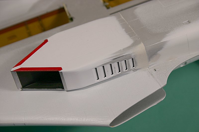
The area between the top front of the intakes and the lower wing – where the wedge-shaped boundary layer diverter is moulded – cannot be accessed once the intake is in place, so this was sprayed white – as were the intakes themselves.
The front portion of the central divider, the front of the sidewalls and the top leading edge of the ‘roof’ Vee were all painted silver to replicate the natural metal in these areas.
The lower leading edge Vee is depicted with a raised lip – this is correct and should be painted red to represent the covers put in place the prevent head injuries from the sharp lips.
Note that if you want to depict your Blackjack in flight, or with the engines running, you should remove this raised lip and paint it silver.
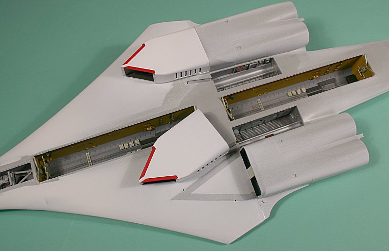
The assembled and painted intakes were then cemented in place on the lower wing – I had the use a little filler to blend them in to the ‘fixed’ rear nacelles, but overall, the fit wasn’t too bad.
Cockpit Canopy
Trumpeter has moulded the kit canopy as a single part – including the parts of the surrounding airframe. This is an excellent way of doing things – and avoids having to insert individual windows with all the attendant problems that it brings.
Having polished the canopy, it was cemented in place on the fuselage – but try as I might, I could not avoid having a distinct ‘step’ between the glazing and the airframe.
I filled in the join between canopy and airframe – and thought that I had got a good seam.
It was then that I realised that in my haste, I had forgotten to add the overhead console inside the canopy – parts P9 & P13!
Luckily, it is not very obvious that it is missing – so if you don’t tell anyone, I won’t.
I masked off the whole canopy area and applied a coat of white primer to check that seam. The white paint revealed what I had feared – the canopy is actually narrower than the surrounding fuselage and no amount of filling was going to hide it.
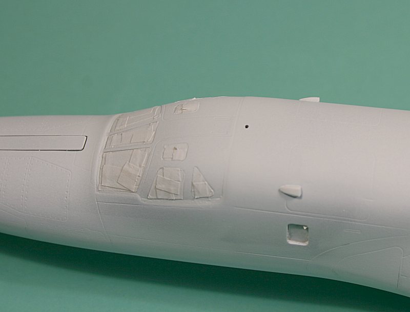
The only solution is to carefully sand away the fuselage – particularly at the sides where it meets the canopy and the raised ‘lip’ in front of the windscreen.
It didn’t take much sanding – but the end results are well worth it – there should be no visible joint between canopy and fuselage – it is all part of the same structure.
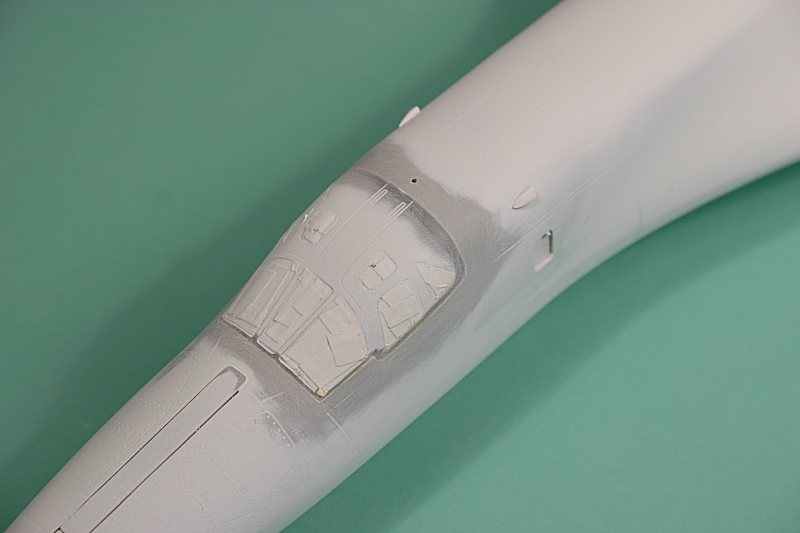
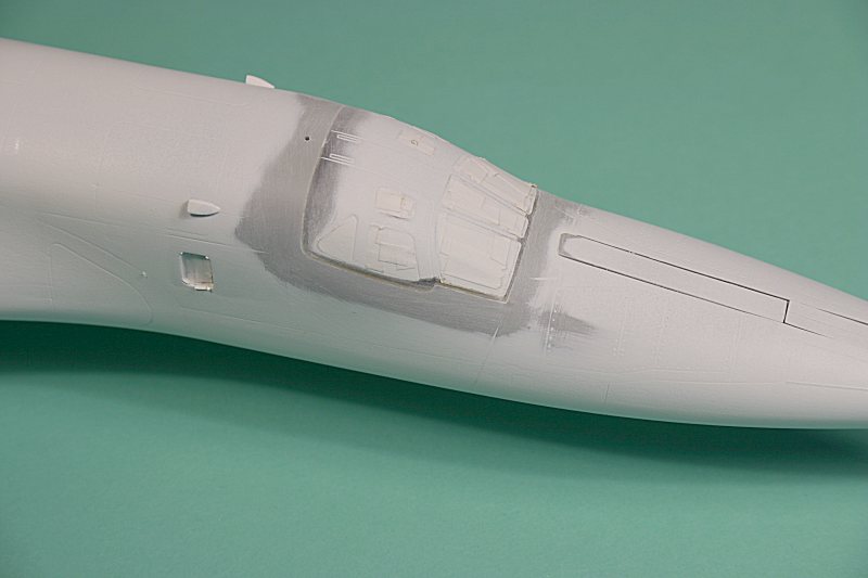
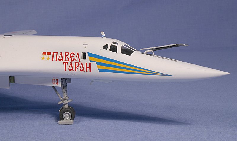
I also added two rear-view mirrors, made from scrap plastic, to the front of the WSO’s hatches.
Not all Tu-160’s have them – they are probably a retrofit – but the Tu-160 I was modelling certainly does have them in place.
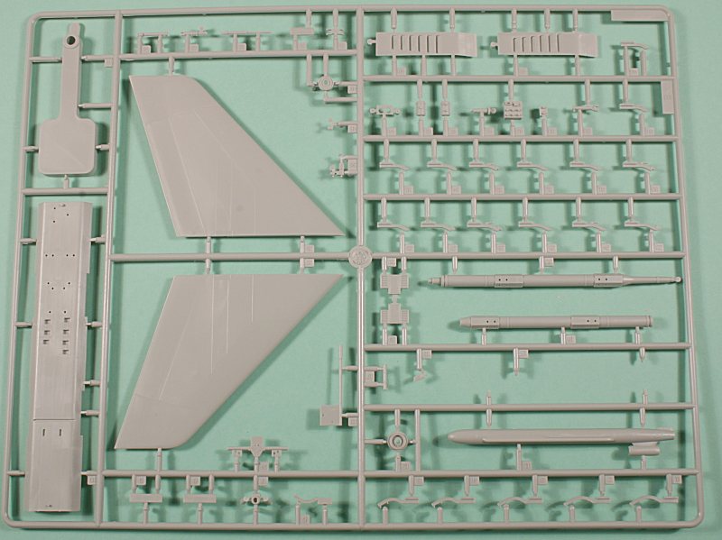
Fin & Rudder
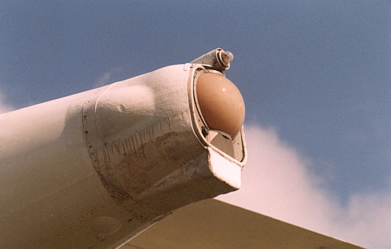
The tail on the Tu-160 consists of a short fixed fin base topped off by a large conical fairing that serves as the mount for the horizontal stabilisers and all-moving vertical fin.
Trumpeter’s instructions show this being assembled and fitted late on in the assembly sequence – just fit it all together and pop it in place, easy as you like – (if you believe that you will believe anything!).

I decided to add it before any detail work was done – and I also modified the stabiliser pivot while I was at it.
The plastic pivot that Trumpeter provides is woefully short – so I made a new one from a length of metal rod.
The short recess moulded into the upper and lower stabiliser halves was reamed out to accommodate the longer metal rod, the stabiliser halves were cemented together – as was the fin ad the parts were set aside until later.
The fin pivot is also short – but it doesn’t matter so much here as there is not the same bending moment being applied to it as is the case with the horizontal stabilisers.
The two halves of the lower fixed base of the fin were cleaned up, cemented together and in turn firmly cemented in place on the upper rear fuselage.
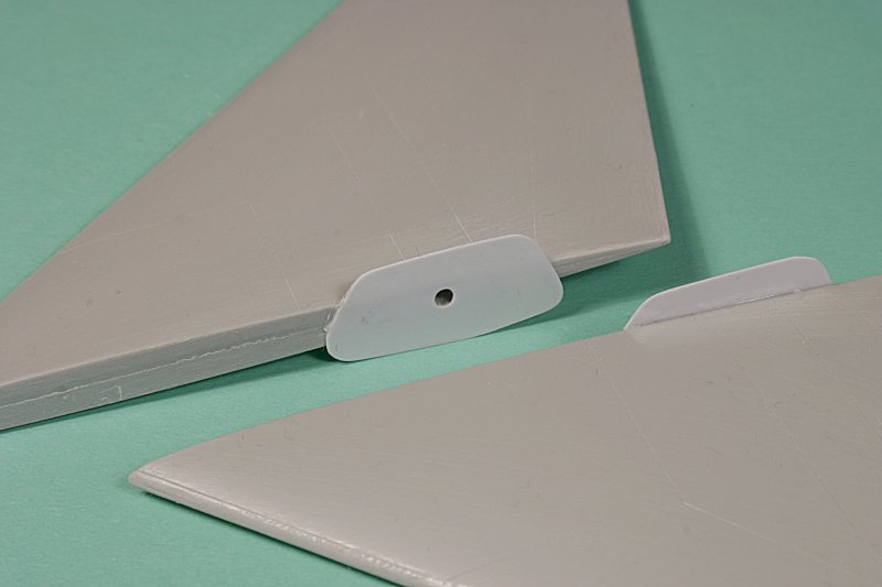
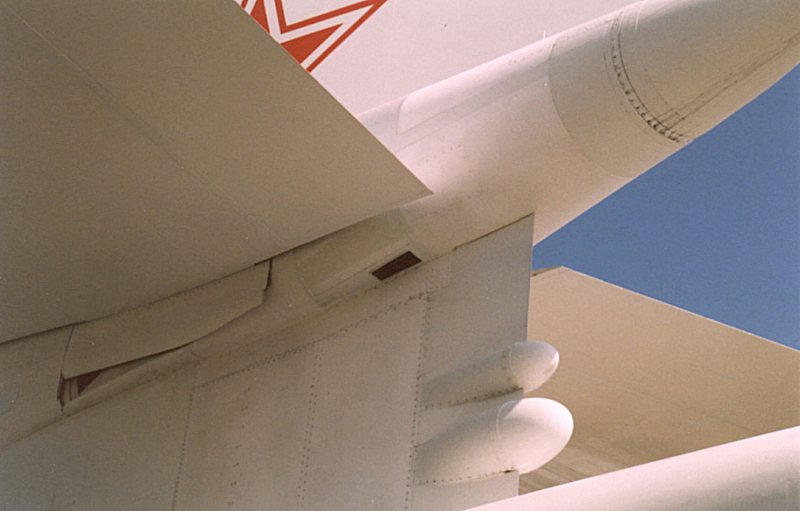
One feature missing from Trumpeter’s Tu-160 is the distinctive ‘rubbing plate’ fitted between the horizontal stabiliser and the fin pivot.
The shape of this plate is engraved into the bullet fairing where the stabiliser fits, but in reality it is a separate part that rotates with the stabiliser – in the same manner as seen on a Harrier.
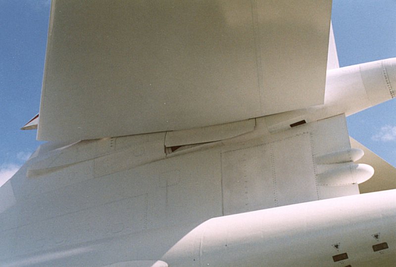
Taking the shape from photos and the engraving, I fashioned new ones from thin plastic card and attached them to the roots of the stabilisers where the pivot points were.
Strictly speaking, there should be a recess inside the bullet fairing that is exposed when the stabiliser and rubbing plate rotates, but I did not add this feature…
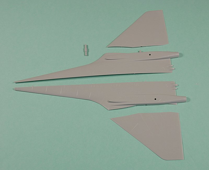
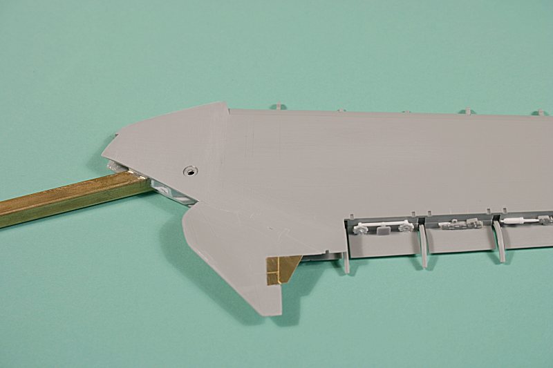
Back to the Wings
Going back to the wings - I had left them partly assembled with the wing spars in place and the wing roots sanded down so that they slid perfectly into place within the now-completed fuselage.
I was pleased with the way that I could fit and remove them for storage and transport, so it was now time to add all that slat and flap detail.
As mentioned previously, Trumpeter have provided a crude mechanism to allow the wings to sweep, but unless they are built with the slats and flaps retracted, the wings cannot be swept anyway.
If you want to build the wings with retracted slats and flaps, you are going to face problems with closing it all up and eliminating all the joint lines – it is just not designed to be built that way – so why have a swing mechanism in the first place.
Much better to model it with all that flappery out and deployed – but there are lots of parts to tackle….
The leading-edge slats are in five sections – each separate section comprising an upper and lower half. That’s ten parts per wing.
The trailing-edge flaps are even more complex, with three sections each made up from an upper and lower flap and three slotted sections.
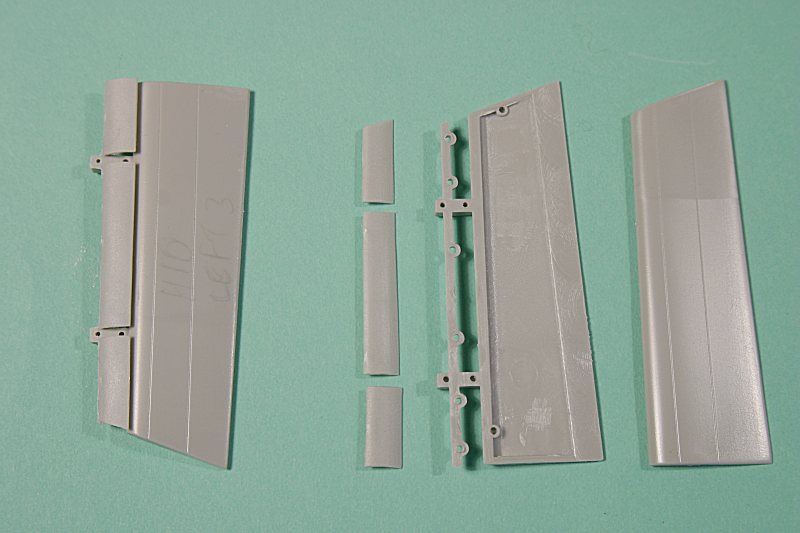
A fourth section, the drooping aileron, is made up from an upper and lower half. That’s 17 flap parts per wing!
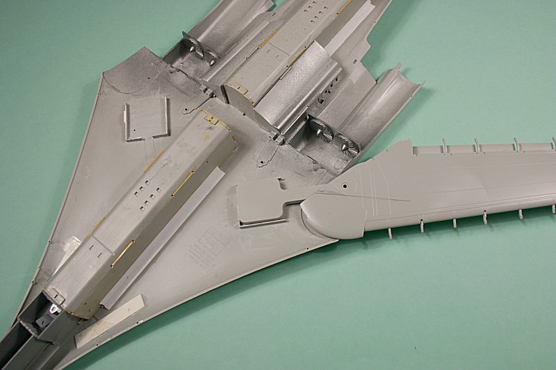
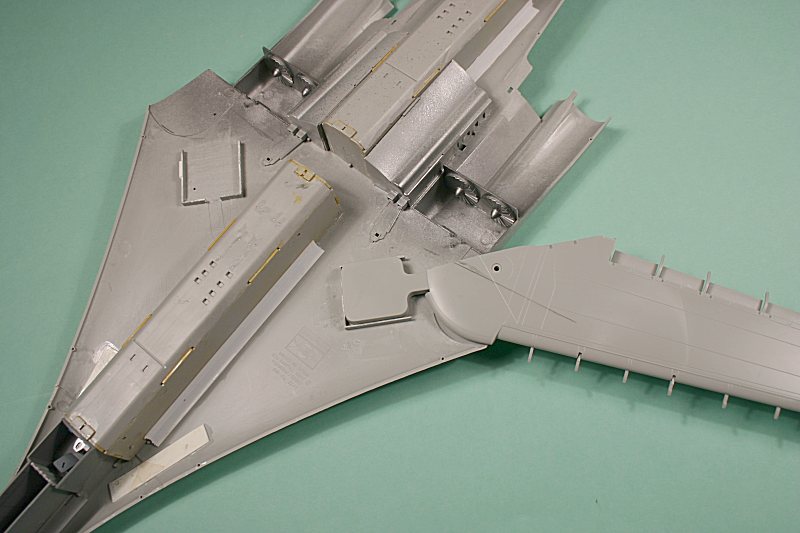
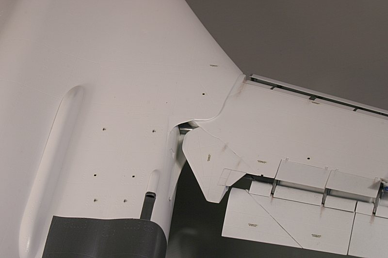
Finally, there are five spoilers per wing plus the two wing root sections, each made up from four parts plus an etched-brass insert.
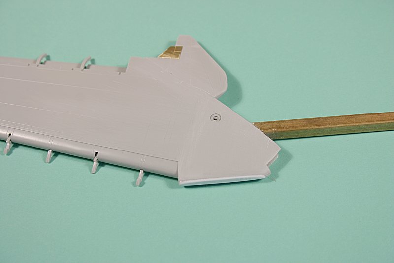
The photo above shows the amount of plastic that has to be removed to allow the wing root ‘knuckle’ to slide into the wing slot.
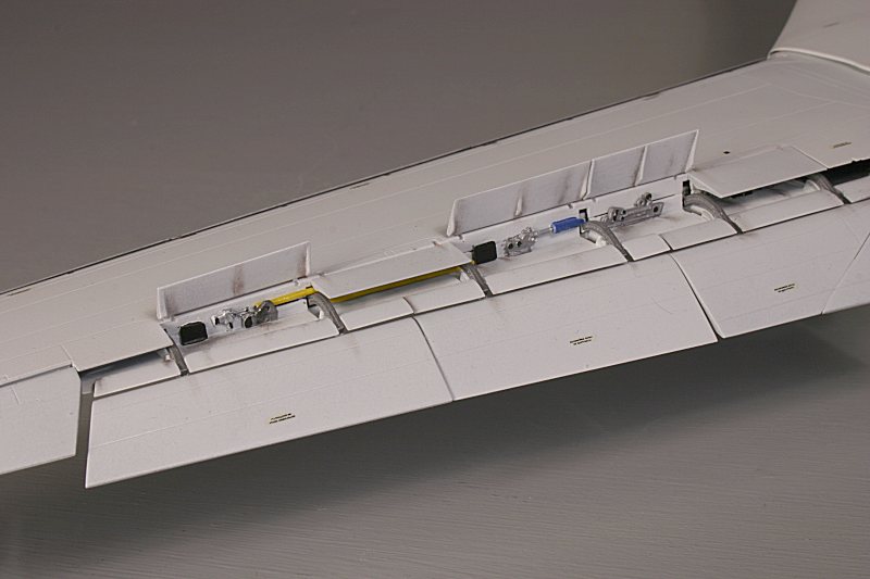
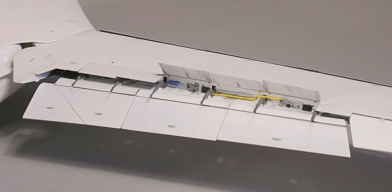
The spoilers can be fitted in the raised or lowered position, but if raised, the inner structure of the wing inside the flap area is exposed – and it is rather bare.
I elected to model my White Swan with some of these ‘feathers’ in the raised position and some lowered – as I had seen in a reference photo. This photo even showed them in an asymmetric configuration – one up and four down on the starboard wing and three up and two down on the port wing – so I would do the same to add some interest.
I have no idea what the inside structure looks like – I couldn’t find a single decent photograph showing this area – but I felt it needed some sort of ‘busying up’.
I added some parts from the spares box – and some piping from electrical wire – just enough to give some hint of internal ‘workings’ – all totally fictitious of course.
If the spoilers are cemented in the closed position, this area is reasonably well hidden.
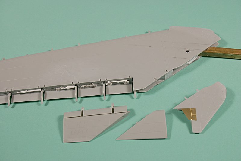
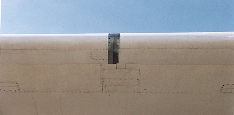
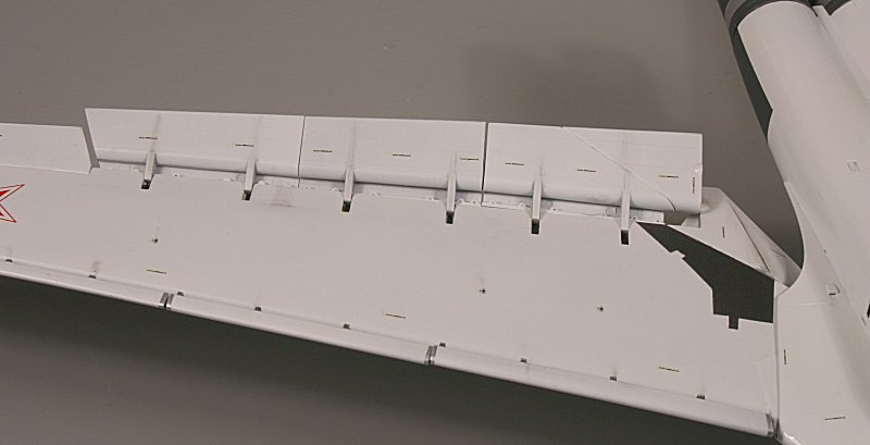
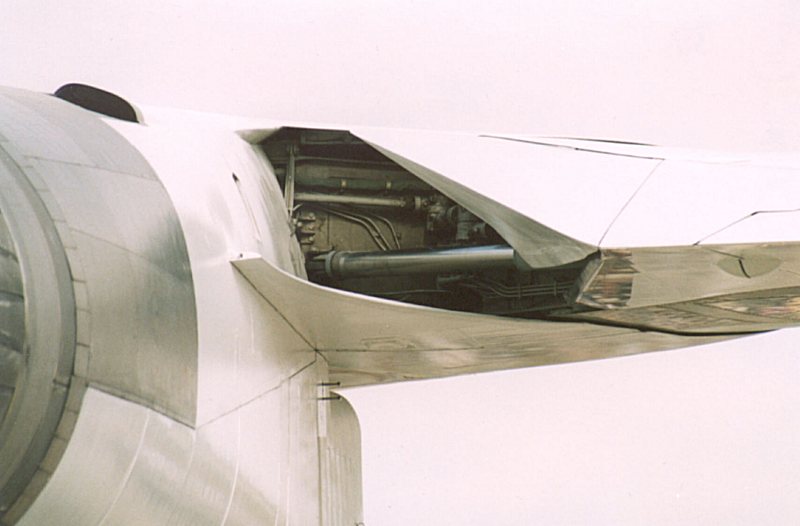
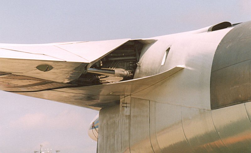
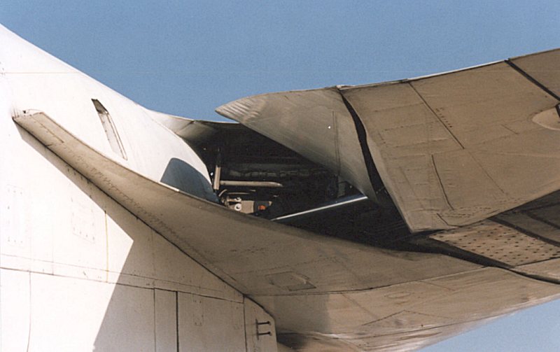
This shows how the wing root hinged segment works on the real thing – the middle section ‘detaches’ from the left flap section – and ‘attaches’ to the right-hand section. When the wing folds, these two sections fold up to form a single fence.
This photo has the middle section attached to the left hand flap section – and the wing root section folded flat onto the wing root.
The above shows the folding wing root section on the starboard wing.
The completed wings – minus the flaps, slat & spoilers – were sprayed with a can of acrylic car paint – White Plastic Primer first, followed by a light rubbing down and a final coat of Appliance White to give a smooth semi-gloss finish.
These car sprays are from a well-known chain of car accessory stores here in the UK called Halfords and they are a boon to modellers.
I use them a lot – particularly their various silvers and their Grey & White Plastic primers. The Appliance White gives a superb, hard, semi-gloss white finish that does not fade or yellow. On a model the size of the Tu-160, it is so easy to achieve an all over white finish without having to resort to an airbrush – and just imagine how many tins of Humbrol gloss white it would take to cover the Blackjack?
With the main parts of the wings painted, the dozens of flap and slat actuators were painted dark metallic silver.
The area above each slat actuator, inside the wing and covered by the slats when retracted, has no less than fourteen metallic strips – one per actuator.
They were depicted on my model by short lengths of silver-painted decal strip.
The assembled slats were painted before being attached to the wings – white on the outside, silver inside and with a section of metallic rubbing strip at the end of each section.
This photos shows the metallic sections on the real Tu-160 slats
The flap sections were also pre-painted – this time just plain white – and attached in the lowered position to the wing trailing edge.
Finally, the ten spoilers – five per wing – were attached, some in the fully raised position, some lowered – just like the photograph.
Trumpeter provide a wing sweep actuating ram (part E-13) which, in their construction sequence, is added when the wings are inserted prior to the fuselage being assembled.
Because of my modifications to allow for removable wings, I made new actuating rams from aluminium tubing and fitted them inside the wing next to the spar - where they are visible when the wings are attached.
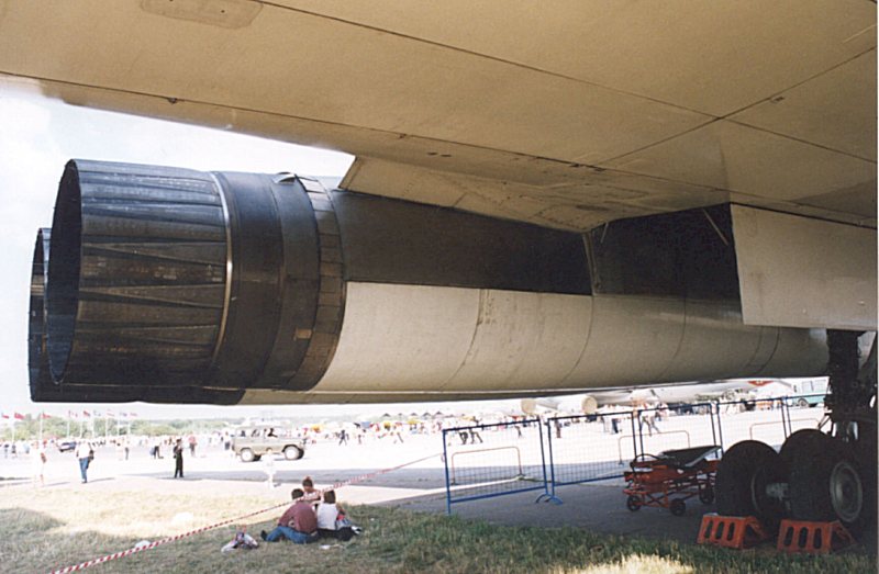
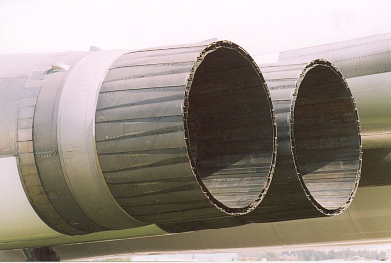
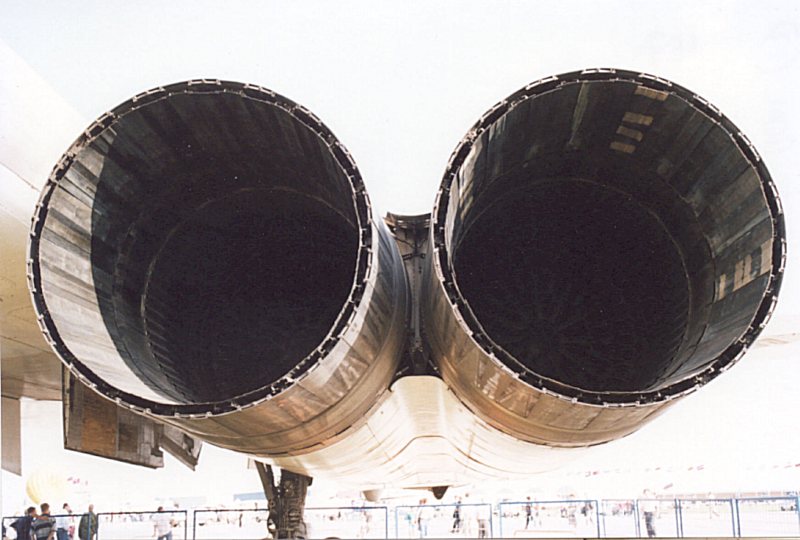
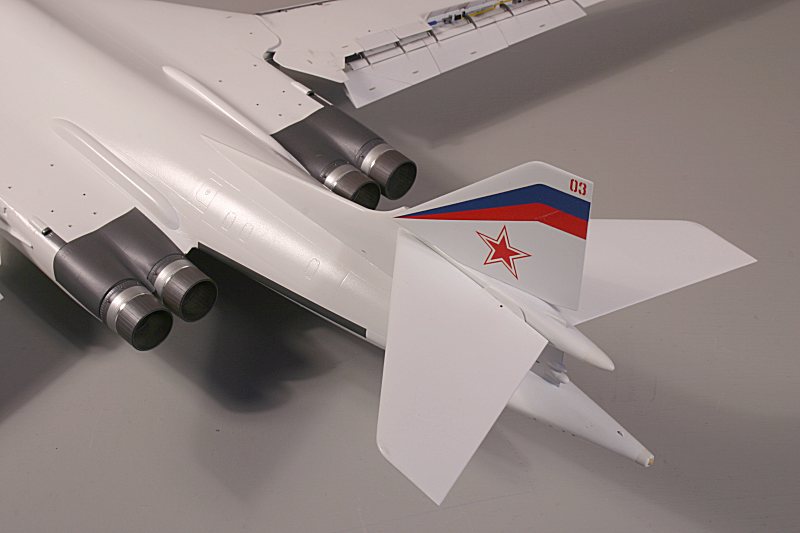
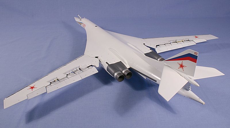
Engine Nozzles
Completing the main fuselage construction are the engine exhaust nozzles – all four of them.
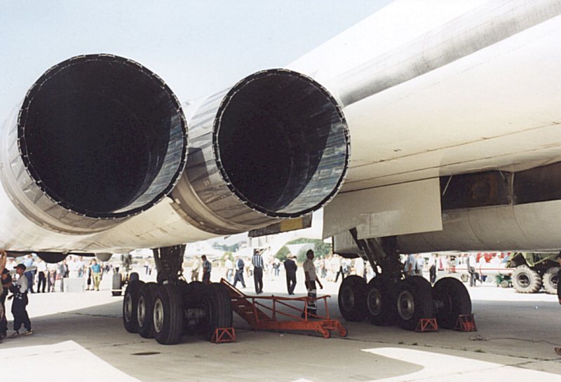
They are made up from no less than SIX parts per nozzle and faithfully represent the engine exhausts of the mighty 55,115lb static thrust (in reheat) Kuznetsov NK-32 three-spool turbofan engine.
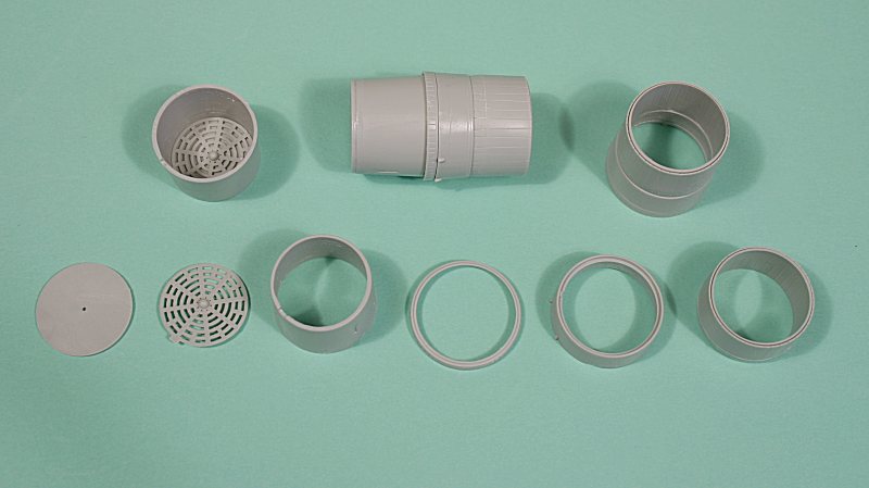
The nozzles – and the surrounding engine trunking on the airframe – were airbrushed with Humbol Polished Steel with a Polished Aluminium middle section.
After they had been buffed up, a coat of matt varnish was applied to replicate the dull appearance of the real thing.
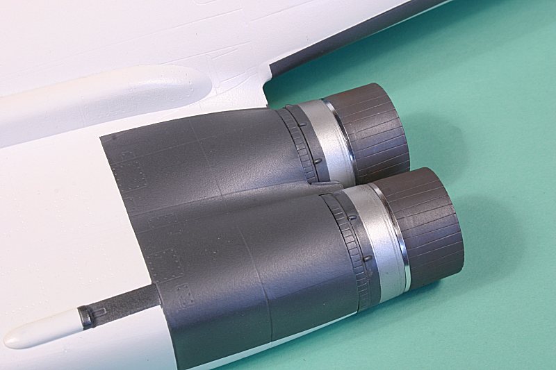
The distinctive ring of highly-polished steel was applied using a strip of chrome tape.
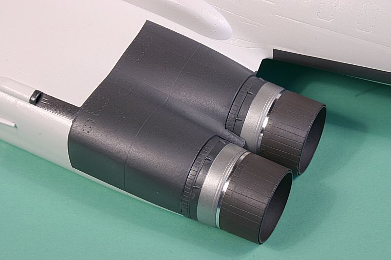
The completed nozzles simply slot into place in the trunking after all other painting and decaling is completed.
Painting
When it comes to a choice of paint schemes, you can have white, white or white!
Actually you could make one of the prototypes in multi-hued natural metal, but you would need to make a few modifications to the airframe.
Operational machines are overall white – but the paint quickly fades to a patchwork appearance that would be interesting to try and replicate.
The white is relieved only by the off-white/very pale grey of the various dielectric panels around the nose and on the leading edge of the blended wing roots.
The Begemot decal sheet (of which more later) gives some great in-depth information about the colour schemes of each individual Tu-160 currently in service – so you can accurately replicate any machine – from a pristine all over gloss white to a decidedly scruffy-looking faded example.
As the wings had already been painted, all that was left to paint was the main fuselage assembly – with the base of the fin attached.
The cockpit windows, the camera aperture in the lower nose, the polished steel engine trunking, both weapons bays and the undercarriage bays were blanked off in preparation for the white paint.
On a model of this size, it would take dozens of small tins of model paint to airbrush, but fortunately, here in the UK there is a ready-made alternative – acrylic car sprays.
I used a can of Halfords White Plastic Primer as an undercoat, before giving the whole model a top coat of the same companies Appliance White.
The White Plastic Primer gives a superb, smooth, matt white base which, after a light sanding, provides a great canvas for the gloss white top coat. Nothing could be easier!
The Halfords white gives a great, intense white appearance, does not yellow with age and provides a smooth glossy surface for the decals.
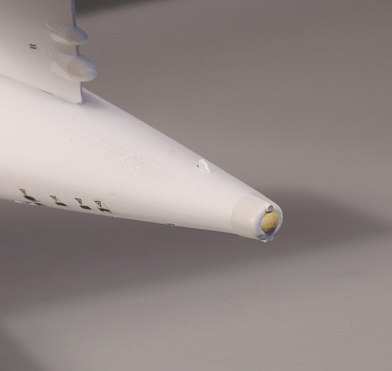
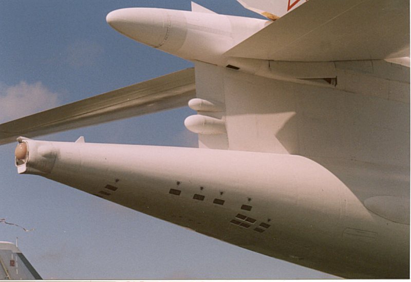
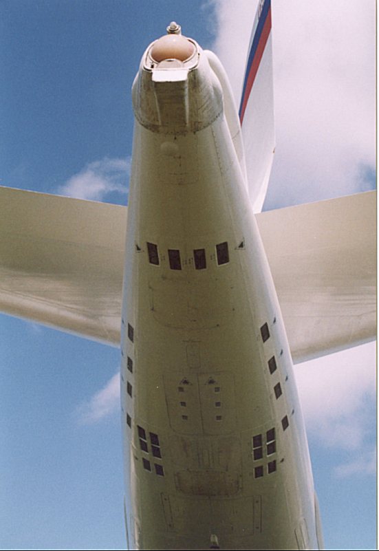
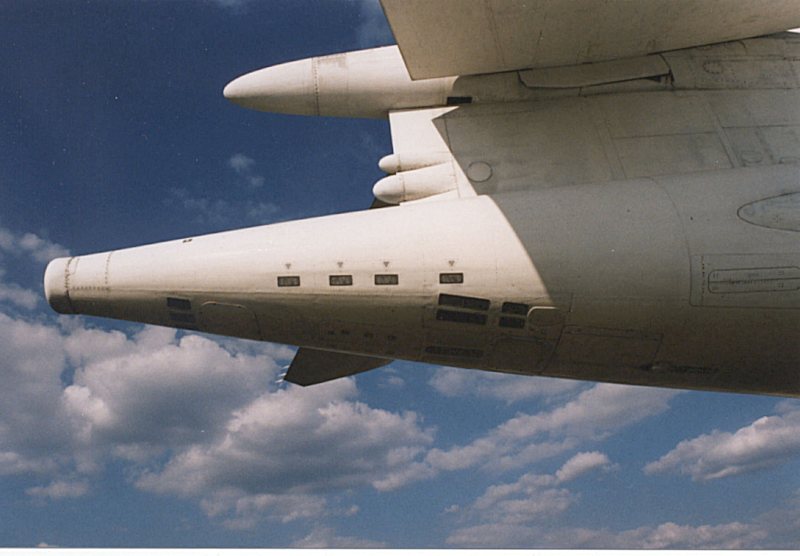
The only other painting required is the tan-coloured tailcone of the ESM equipment, the matt-white rear of the fin/tailplane bullet and the two bullet fairings below it, the dark grey circular antenna set into the upper fuselage (kit part L4), the dark metallic conduits either side of the rear fuselage and the numerous black rectangles of the three-round APP-50 chaff/flare dispensers built into the underside of the rear fuselage.
Markings
Now we come to the interesting bit!
Something to break up that overall white appearance!
Trumpeter provide a perfectly adequate decal sheet that gives markings for two Tu-160’s – bort 06 ‘Ilya Mouromets’ and bort 02 ‘Vasiliy Reshetnikov’.
The colour decal placement diagram correctly depicts only bort 06 as having the ‘full-up’ colour scheme – bort 02 was just plain white with only the name in Cyrillic on the nose.
(Note that later in 2003, bort 02 also had the nose and fin chevrons applied, but the fin chevron was the later, ‘cranked’ style).
The after-market decal manufacturers were quick off the mark to provide alternative schemes – the first of which was Authentic Decals with a sheet containing six red stars, four Ukrainian Blue/Yellow roundels plus two fin Tridents, the ‘cranked’ blue/red fin chevron and the Cyrillic names for nine Engels-based Tu-160’s – making ten alternative finishes in all.
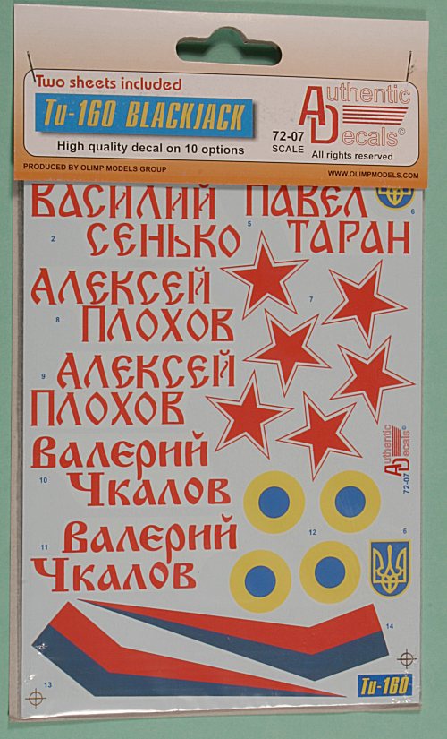
The instruction sheet provides decal placement profiles, a list of source material and a ‘painting guide’ (which merely says ‘All surfaces white – and quotes Humbrol 34 or Testors 1768).
Following hot on the heels of the Authentic Decals set is a superb set from the Russian firm of Begemot (Behemoth or Hippopotamus).
This includes the national markings of Russia and Ukraine - six Russian red stars, four Ukrainian roundels plus the trident fin flash, BOTH styles of fin chevron – the early style wedge shape and newer ‘cranked’ style, TWO styles of nose chevron and two Imperial Eagles.
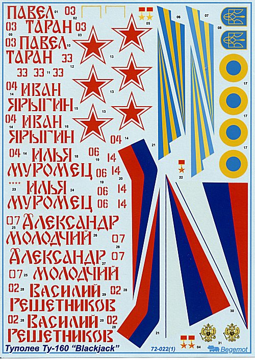
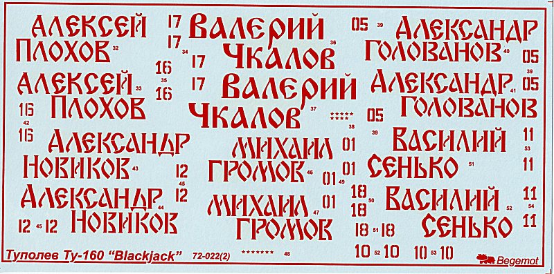
The rest of the sheet comprises the bort number and names of no less than THIRTEEN named Blackjacks plus a Ukrainian example.
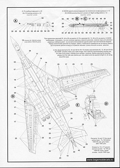
More important than the decal choices is the comprehensive placement guide consisting of two double-sided A3 pages with side, top and bottom drawings with a paint colour guide.
Colour notes are included giving details of the interior of the weapons bays, undercarriage bays, ESM aerials etc - they even provide details of how the gloss white paint fades to matt in certain areas.
This is followed by side profiles that give a potted history and complete colour notes for each machine.
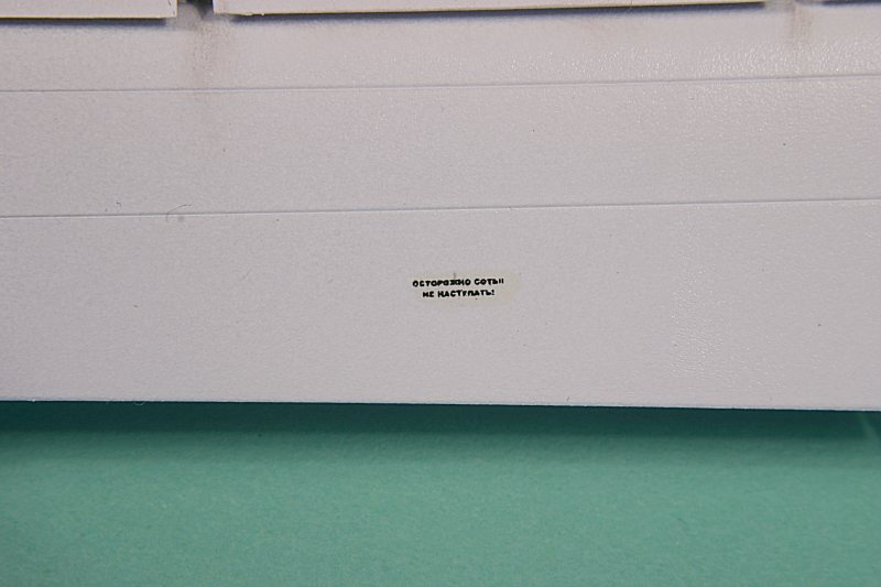
As if all that information were not enough, Begemot have released a separate decal sheet covering the Tu-160’s stencil data.
This comprises two sheets of closely-packed stencils – which are perfectly readable under a magnifying glass – with a complete placement guide and comprehensive colour notes.
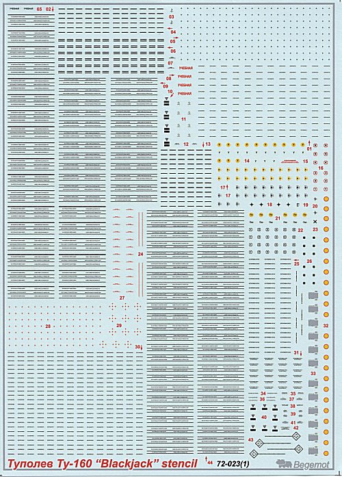
There are even different styles of stencil to cover different periods – pre and post 1995.
In addition to the airframe decals, Begemot provide full decals for the Tu-160’s main armament – the Kh-55 and Kh-55M cruise missiles plus the earlier weapons fit of Kh-15 missiles.
Enough stencils are supplied to make a full-up load of 12 Kh-55’s and when I tell you that each missile has dozens of small stencils, you will realise just how comprehensive this excellent decal sheet is.
The application of the Begemot stencil data is time consuming – but worth it. They detach from the backing sheet after only a minimum amount of soaking and settle down onto the gloss white surface perfectly.
I used a drop of Johnson’s Klear (Future) under each decal and had no problems at all with silvering.
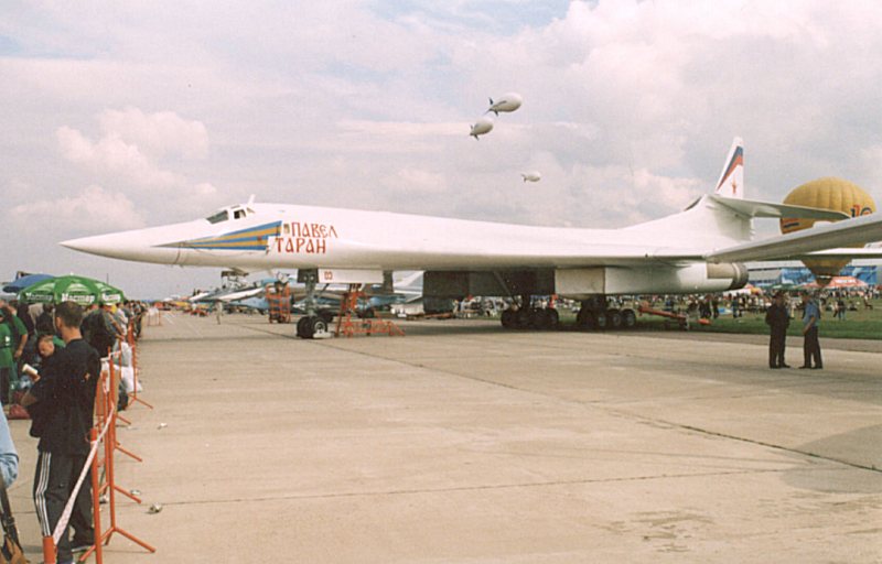
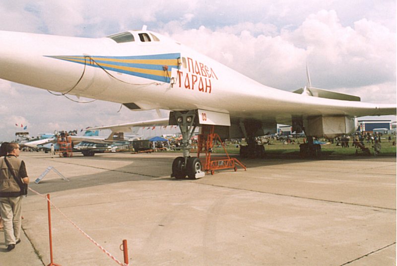
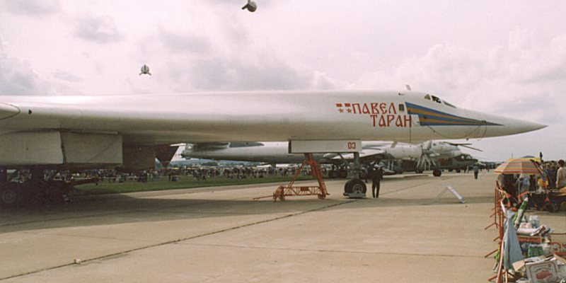
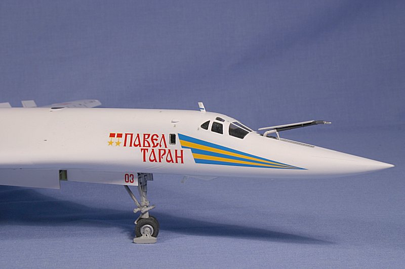
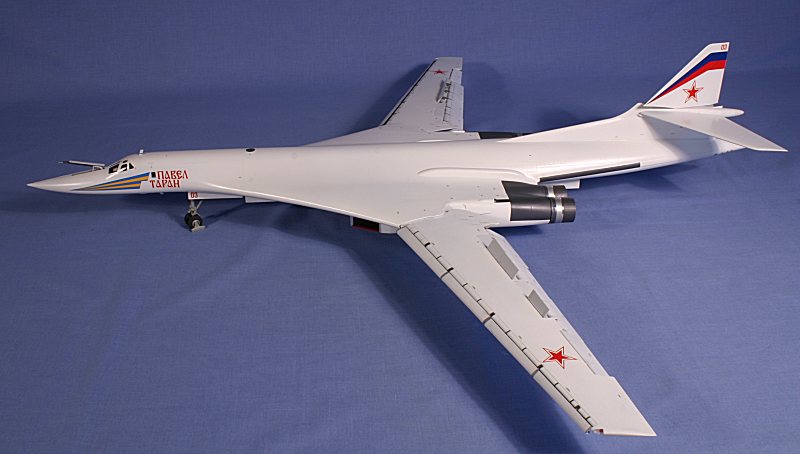
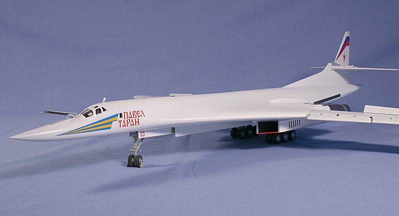
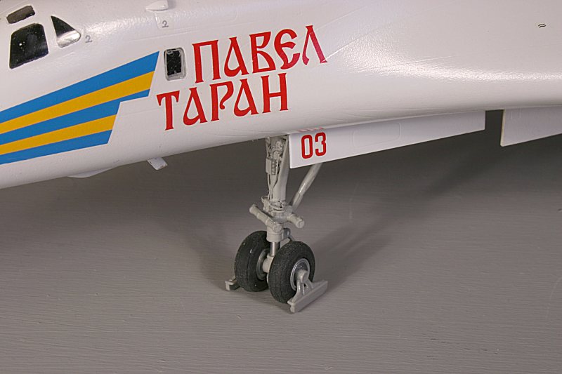
I had already decided on ‘Pavel Taran’ as my ‘named’ White Swan – partly because I had photographed it at Zhukovsky, near Moscow and partly because it had recently been re-painted, had carried President Putin and was in pristine condition
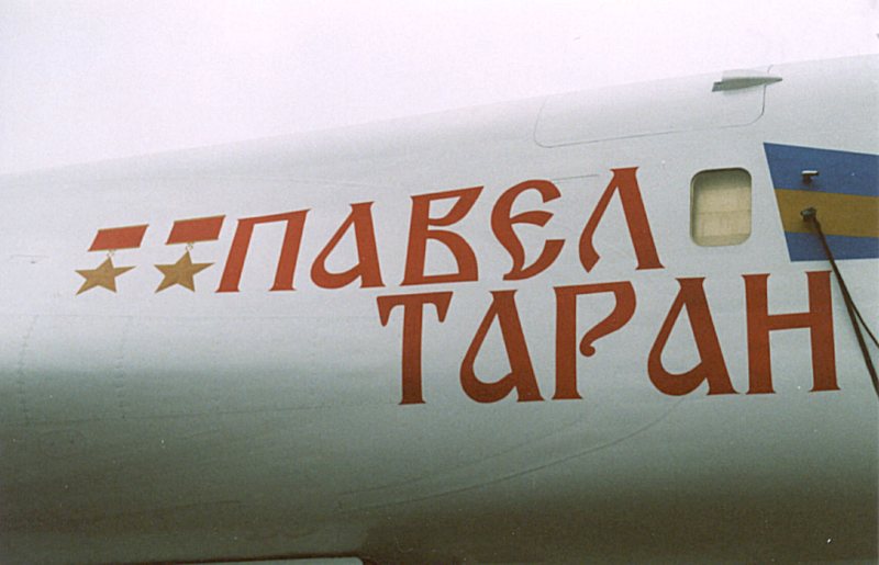
The Begemot decals for the name and the fin chevron were carefully applied – they are extremely thin, but have good colour density – but they do not take kindly to too much handling, so care is needed.
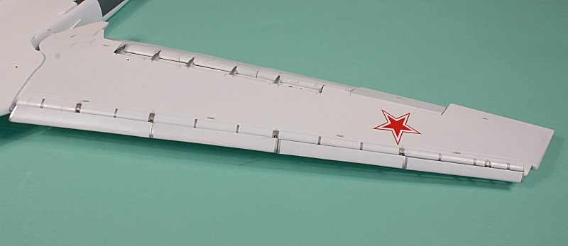
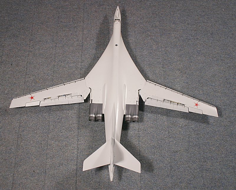
The red bort numbers and the six red stars were also applied – note that the wing stars have the straight top edge of the ‘side arms’ at right angles to the fuselage centreline when the wings are in their intermediate sweep setting.
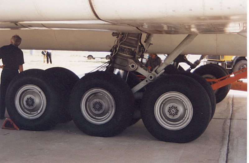
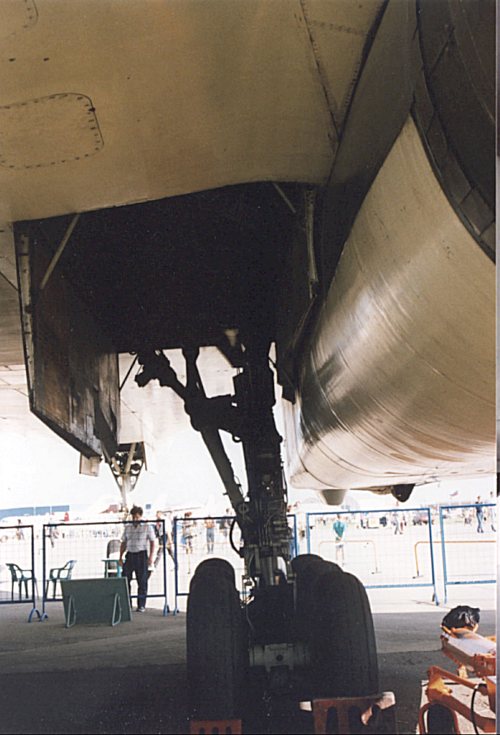
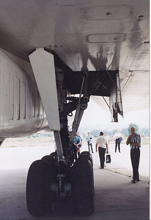
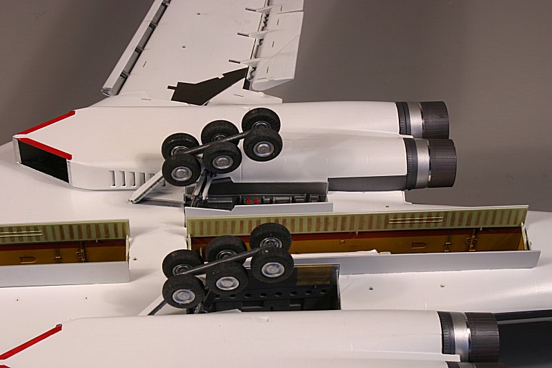
Undercarriage
The main undercarriage on the Tu-160 is quite a complex affair with six wheels on each bogie – and Trumpeter has captured it well.
The kit undercarriage consists of a central strut with a pivot at one end and two locating forks at the other – made from white metal for strength.
To this metal strut is added a detailed ‘cover’ from two halves of plastic – to form the leg proper. Added to that are the various actuating rams and struts to make up the complicated assembly.
Finally the central pivoting bogie beam – made from white metal, with six axles – is added to the leg with a metal pivot pin to allow it to rotate.
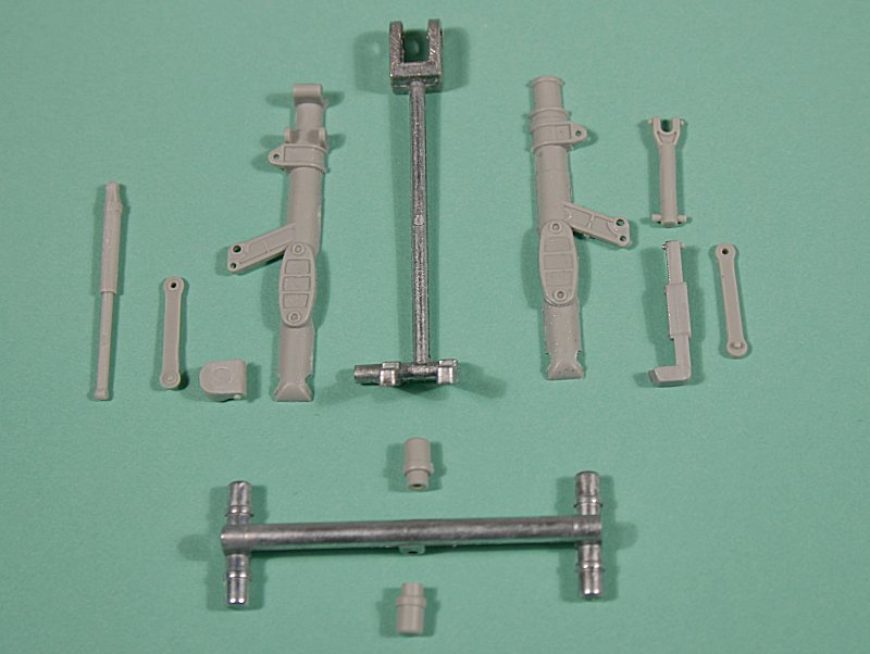
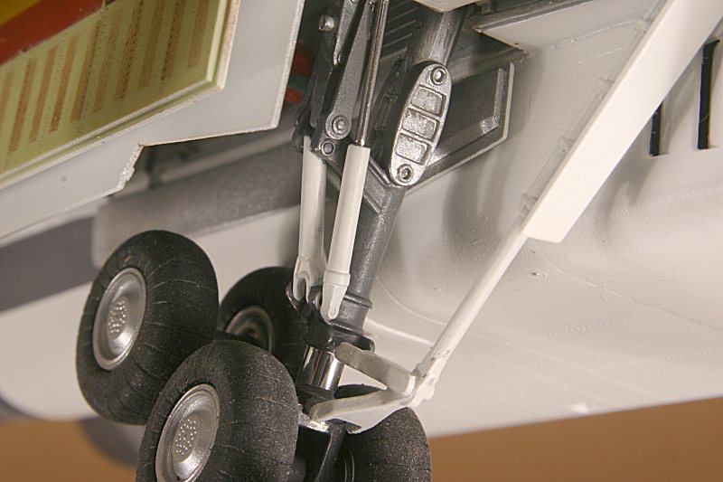
With the combination of a metal internal structure and plastic outer shell and struts, Trumpeter’s undercarriage makes up into a highly detailed sub-assembly that is both strong and delicate-looking at the same time.
The instructions would have you paint it all dark grey – but my photos show that main central leg is dark metallic grey, the upper section is light silver and the struts are light grey.
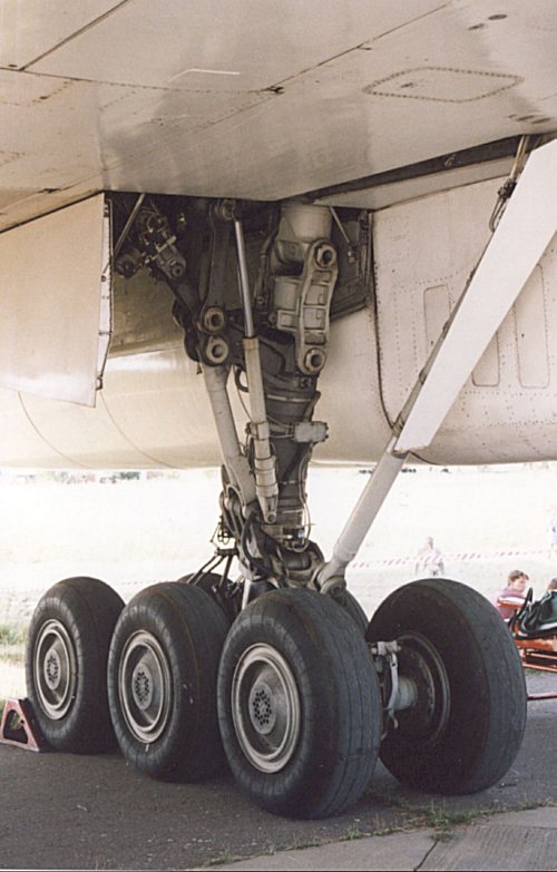
Super-detailers could have a field day adding all the hydraulic brake lines and piping, but I restrained myself to just adding chrome tape around exposed part of the oleo section.
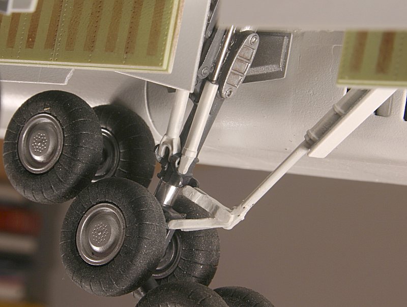
The undercarriage sub-assemblies are added into the wells – with the metal ‘forks’ at the top end of the main legs slotting into square holes in the front bulkhead of the wheel bay.
The undercarriage doors are added next.
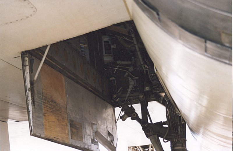
The doors are not ‘Dark gull grey’ on the inner surface as Trumpeter would have it – after painting the outer surfaces white, the inside faces of the outer doors (parts F25 & G25) were painted dull silver, whilst the inner doors (parts F10 & G10) are dull silver with a rectangular section painted in a tan colour. The surfaces of these doors – and in particular the tan section – are well scuffed.
The two forward drag struts, and their associated doors, are added next, as is a central beam (part E54) joining the pivoting bogie to the leg – thereby preventing it from pivoting!
I left this last part off – reasoning that it would be better to let the bogies pivot independently to ensure that all twelve wheels were in contact with the ground before adding it.
It proved difficult to add later with the wheels in place – so it is still not fitted to my model!
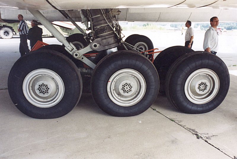
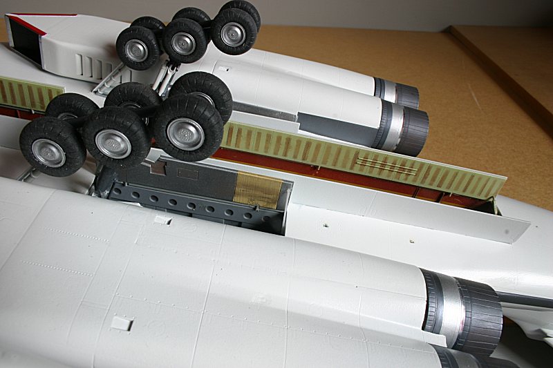
The twelve mainwheels are each made up from three parts for the hub and a rubber tire.
The wheel hubs are bright silver – with a deposit of carbon brake dust. If you are up to it, you could drill out the dozens of tiny ventilating holes in the hubs, or as I did, just highlight them with a wash of Tamiya Smoke.
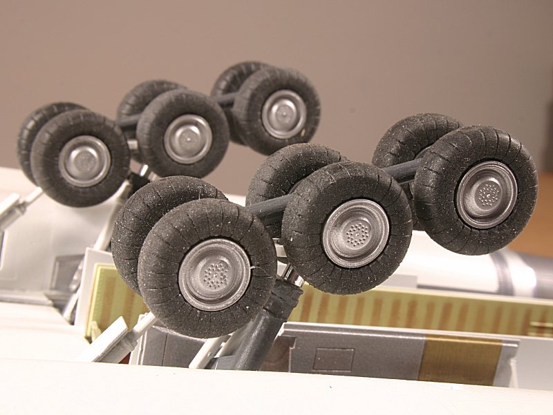
I am ambivalent about the use of rubber for the tires – as long as they are well scrubbed, they look OK, but Trumpeter has overdone the radial ribbing a bit.
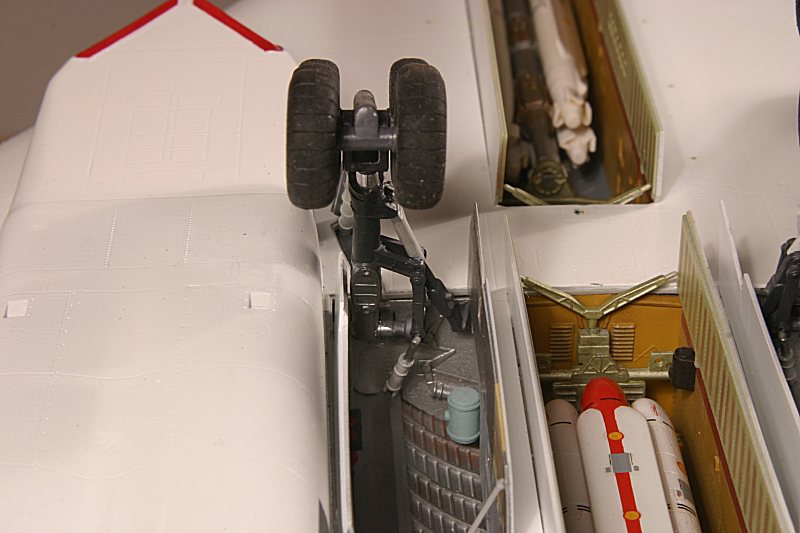
With the nosewheel attached (remember I made it detachable?) the White Swan could finally rest on its legs and spread its wings.
Final Details
All that remained to do was make up and install the two six-round rotary launchers and their associated Kh-55M missiles and add a few aerials.
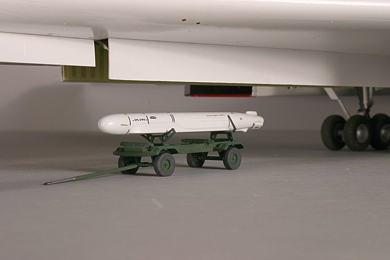
Having made resin copies of the Amodel Kh-55 & Kh-55M cruise missiles, I made up the forward launcher with a full load of five ‘live’ Kh-55M’s – plus one about to be loaded from its transport dolly.
The rear launcher sports three training rounds – two Kh-55’s and a single red-painted Kh-55M training round.
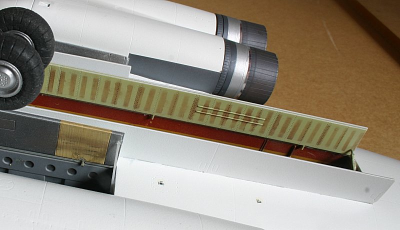
The four weapons bay doors posed a slight problem – they are a pale lime-green colour with brownish vertical ‘stripes’.
I mixed white and yellow with a dash of green until I was satisfied with the shade and airbrushed the inside faces of the four doors.
The vertical stripes are not a solid colour – they look rather ‘washed out’ – so after a marathon masking job, I applied brown pastel chalk and rubbed it in.
With the masking removed, the doors look just like the real thing – at least I think so – so they were applied to the model – along with the undercarriage doors.
Summary
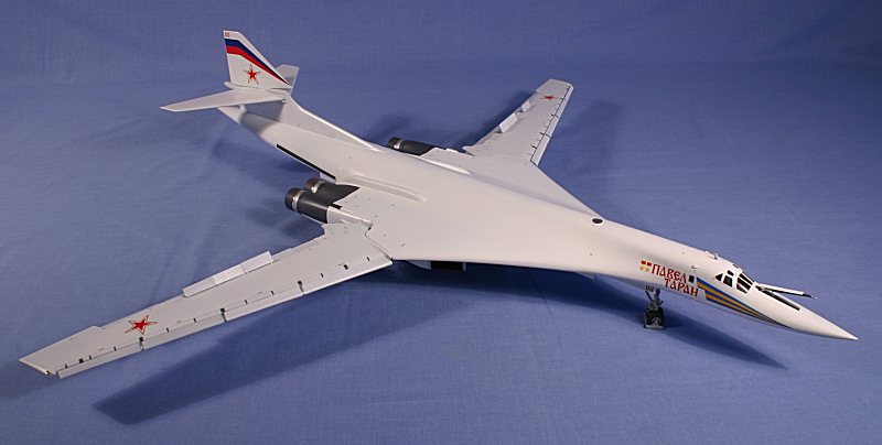
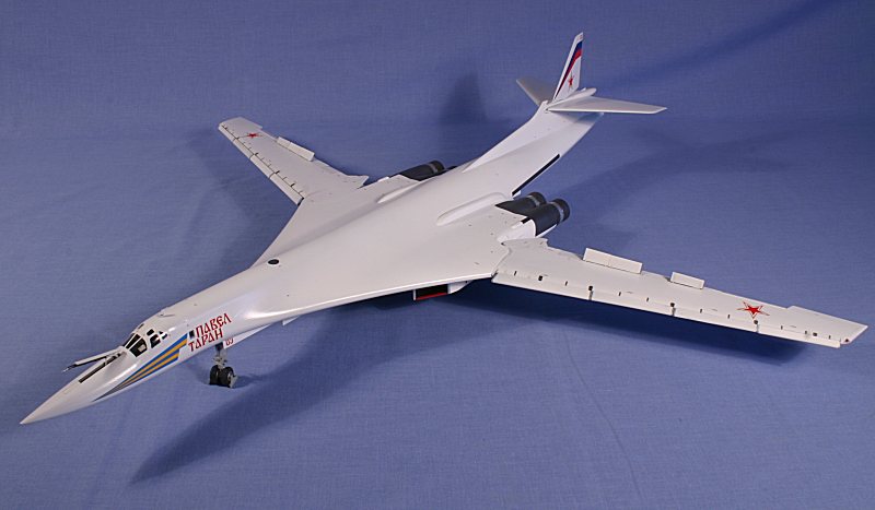
The finished model certainly looks impressive – its size alone ensuring that it attracts attention.
With all the slat-and-flappery deployed and the wings fully forward, I think it looks far more interesting than with it swept and retracted and, add to that the opened weapons bays, it makes for an interesting display.
Trumpeter continue to produce some incredible models – subjects that are close to my heart and which we Soviet aircraft modellers would not have dreamed of being able to make just a few short years ago.
They have given us – in 1:72 scale – the Tu-16 Badger, Tu-95MS & Tu-142 Bear and now the Tu-160 Blackjack.
I do wish they would take more care with their research and attention to accuracy though – the faux pas with the Blackjack’s Kh-55 missiles is inexcusable.
Long may they continue………
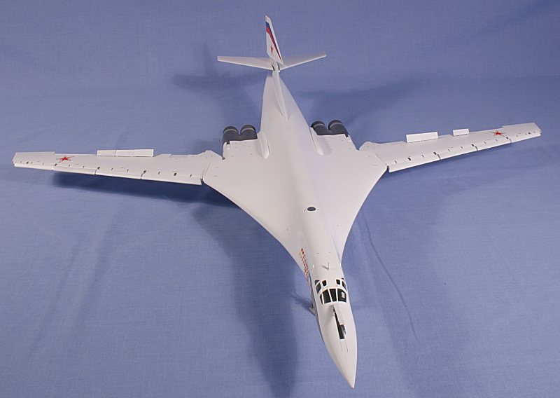
Photos of finished model –
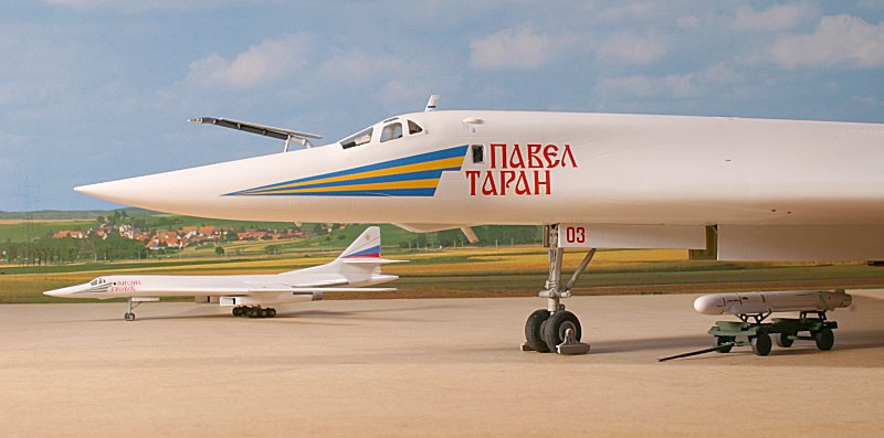
This shows the Amodel Kh-55M missiles – the one on the transport dolley has its wings, tails and engine deployed.....
The Kh-55M about to be loaded into the weapons bay ......
......and on its transport dolley.....
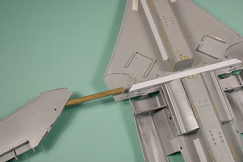
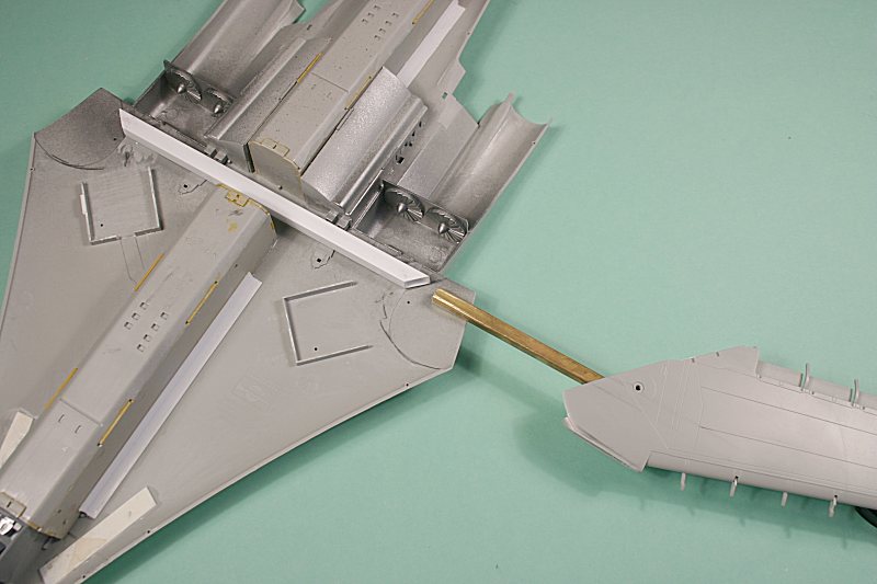
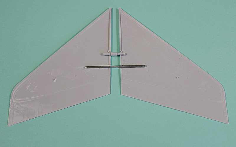
These photos show how I have made the wings detachable for transporting the model to shows.
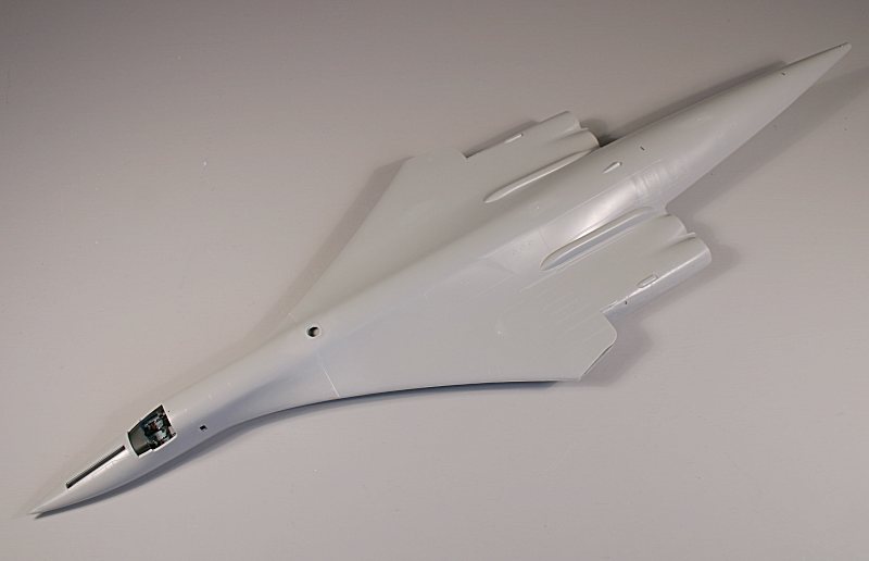
The fuselage....
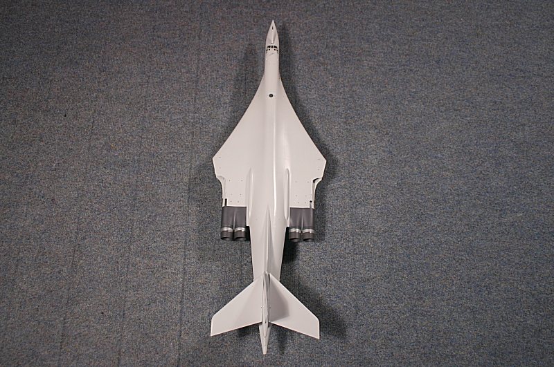
.. how it is transported...
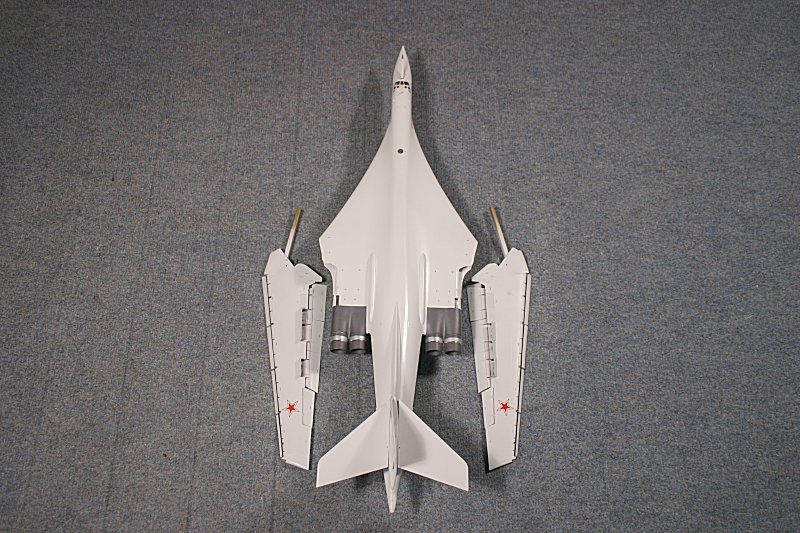
.. the wings ready to be inserted...
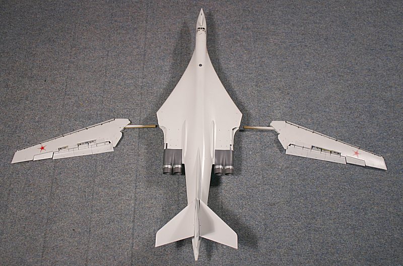
....halfway in place – note how the ‘knuckle’ is cutaway.. ....
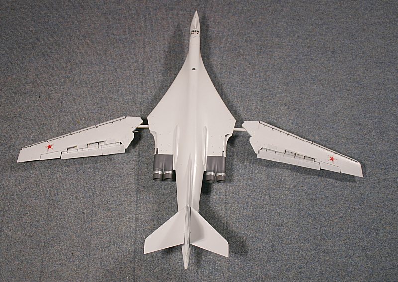
.... the fully-assembled model.....
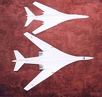
Finally - iIf you ever wondered just how big a Tu-160 is – this is it next to a 1:72 scale Rockwell B-1 !!!
Ken Duffey
July 2008