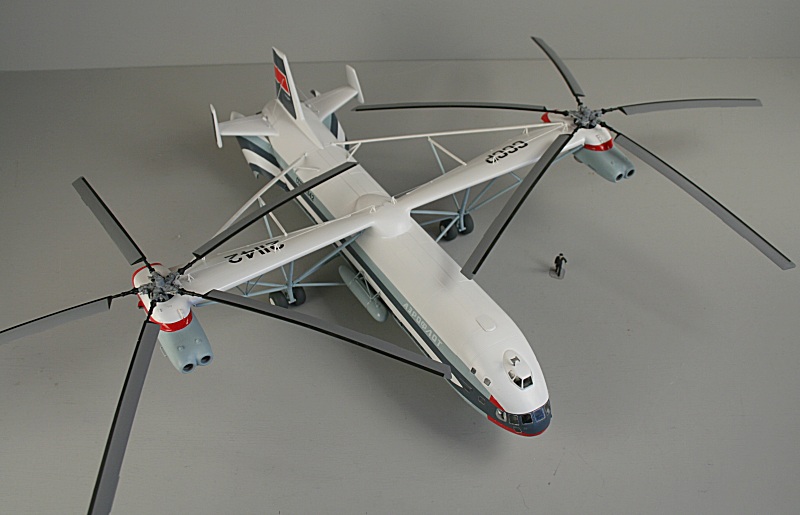
Amodel Mil V-12 'Homer'

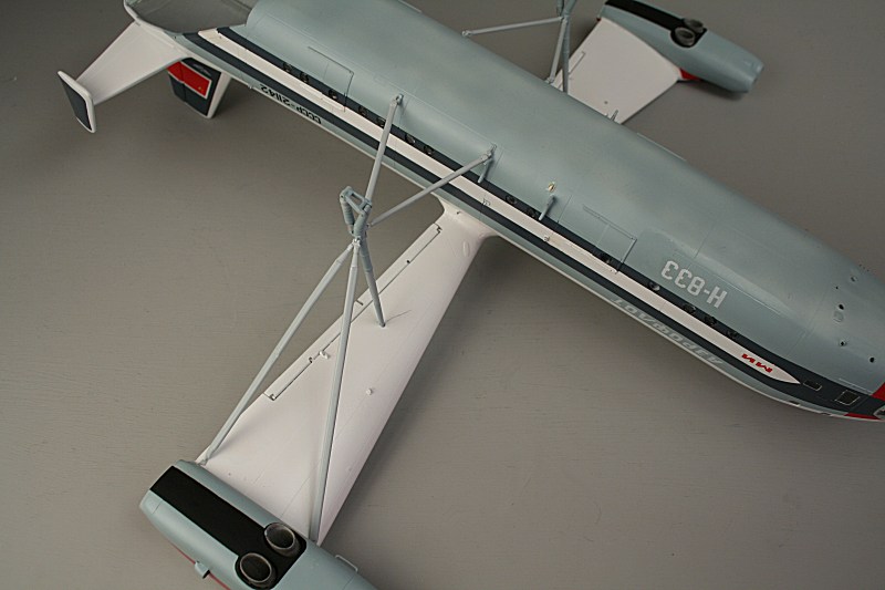
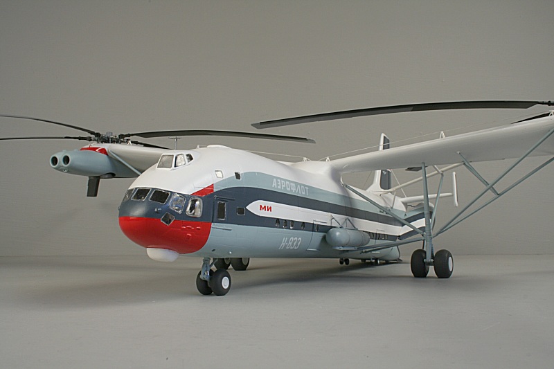
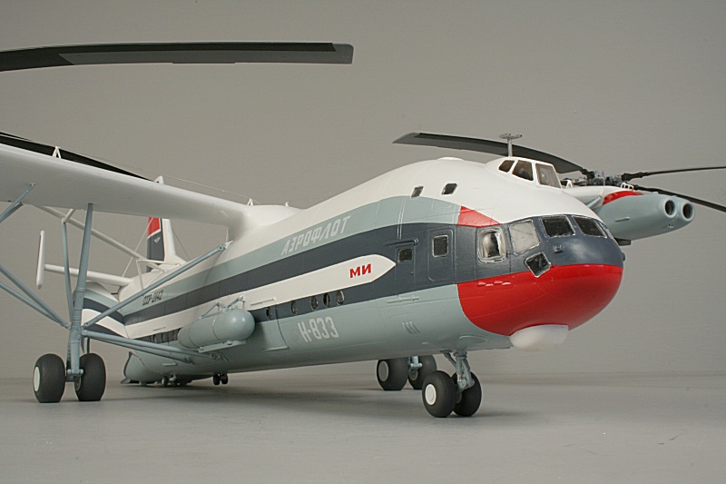
Amodel's box artwork shows the first prototype in the colours it wore for the 1971 Paris Air Show....
...complete with Le Bourget exhibit code - H-833.
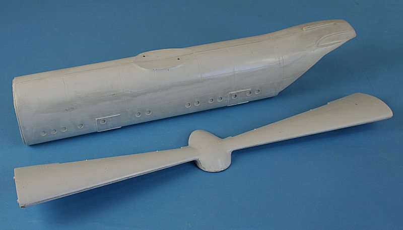
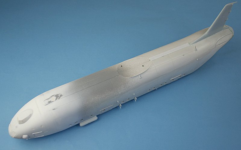
The major components are made in fibreglass-resin - holllow fuselage and solid 'wings'.
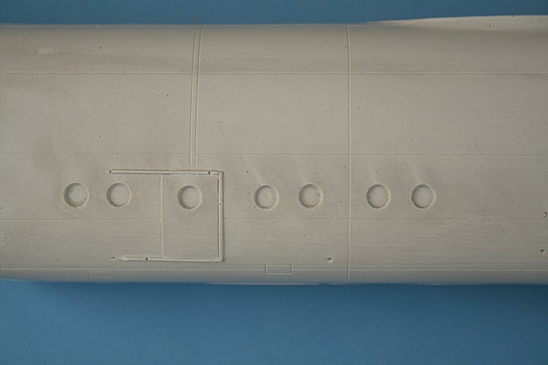
The fibreglas-resin is very dirty-looking bit the surface detail is good - those small dots are embedded dirt, not pinholes!
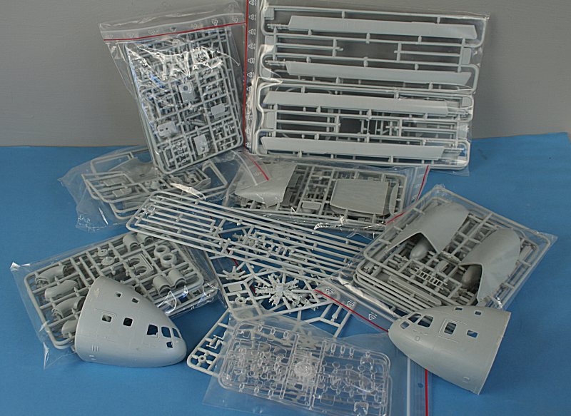
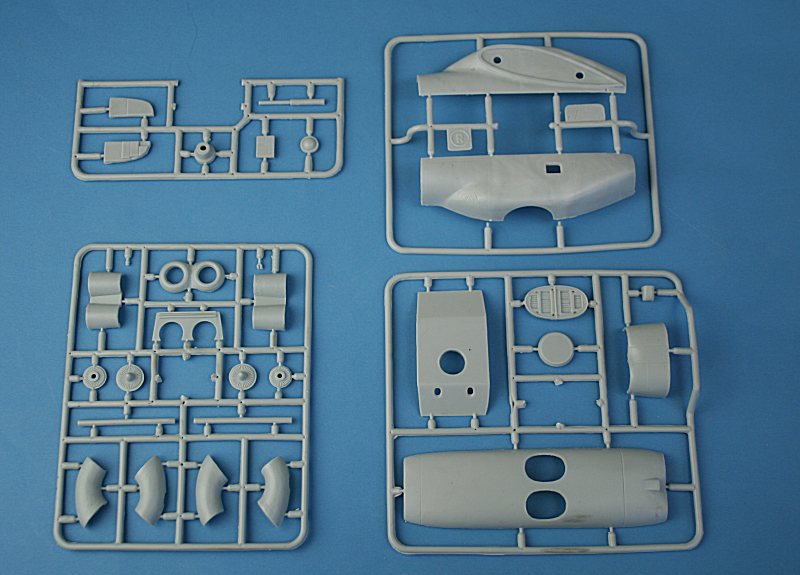
The rest of the kit components are in injection plastic - albeit from low-pressure moulds.
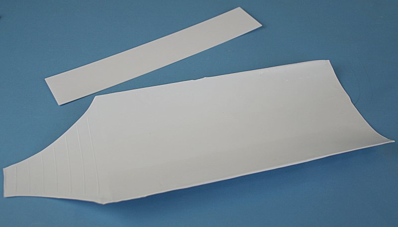
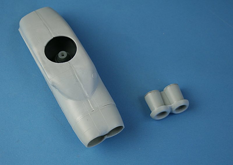
The interior of the fibreglass-resin fuselage is rough impregnated resin - so Amodel provide a sheet of vacform
plastic to be bent round inside the fuselage for the interior lining. A further piece of plastic card provides the floor.
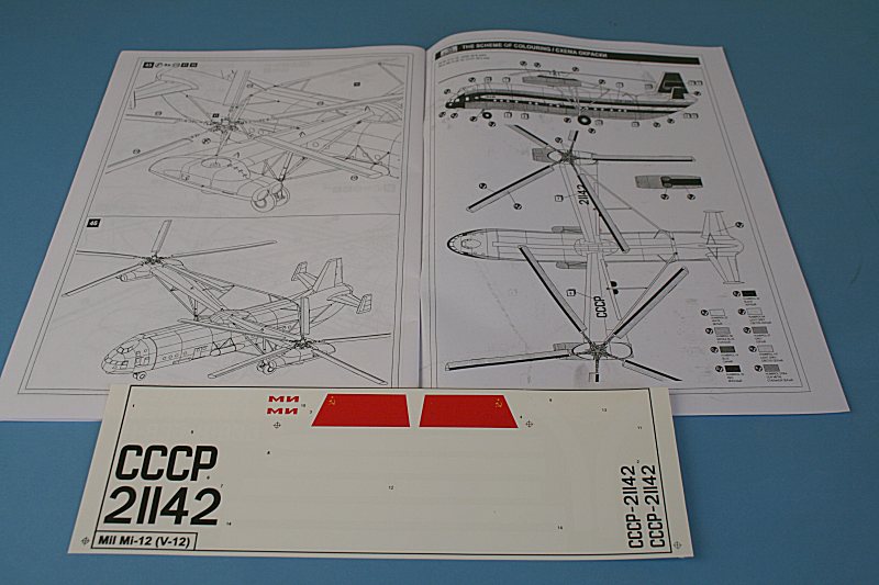
A 23-page instruction 'booklet' is provided - with a brief history, parts layout, colour guide (using Humbrol numbers) and a two-view painting guide.
The decal sheet provides markings for the Paris machine - with white stripes and titling.
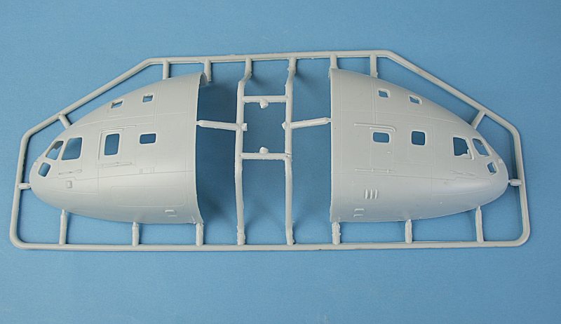
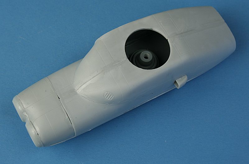
This is the injection-moulded nose section - note the large sprue gates and flash around the starboard window openings.
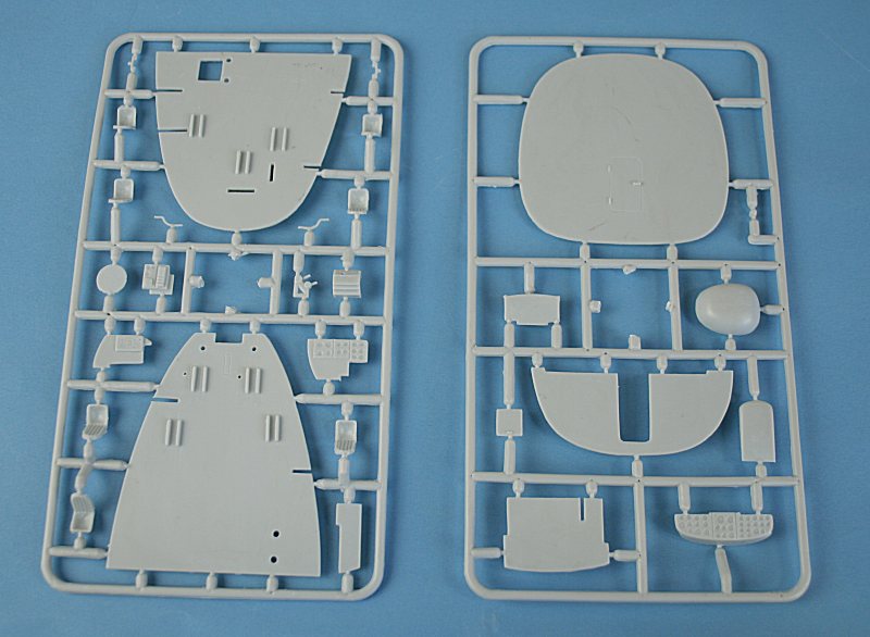
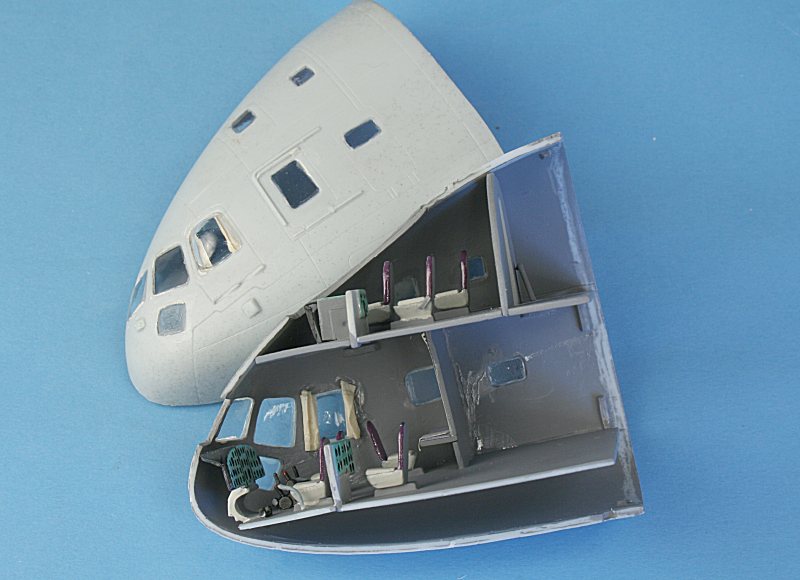
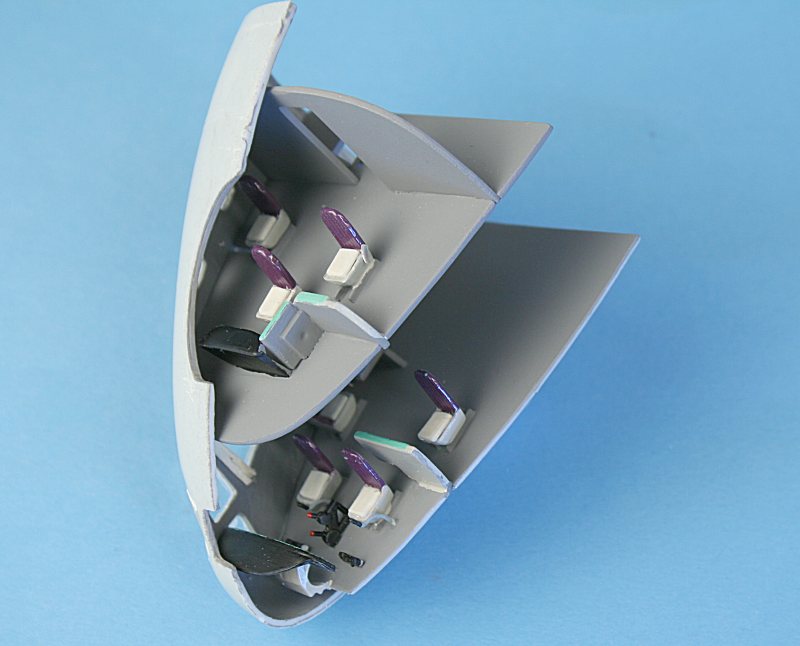
The components for the double-deck crew compartment.
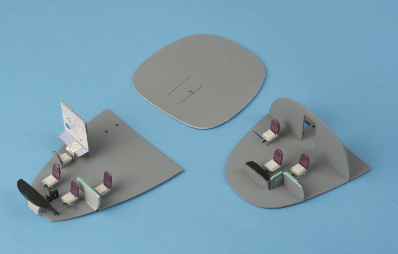
Lower (left) and Upper (right) decks with rear bulkhead. I have added seat cushions and maps on the navigators table.
(actually it is the flight engineers station - the navigator sits upstairs - on the balcony!)
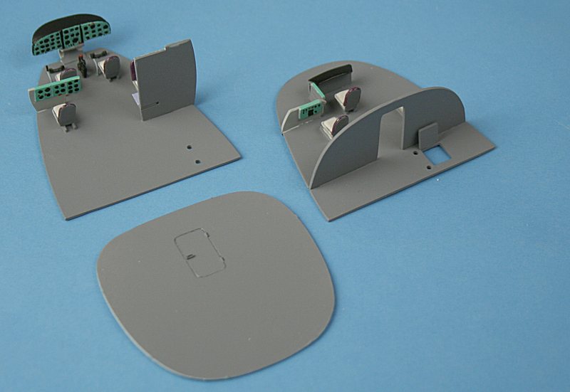
The colours are my own - taken from a couple of poor quality colour photos of the crew stations.
These show purple seat backs and pale grey seats. The interior is quite simplified - but not much can be seen anyway.
The V-12 has the engines & drive trains from TWO Mi-6 'Hook' helicopters.....
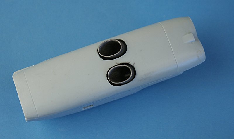
Each of Amodel's engine nacelles is made up from no less than 19 parts - including split jetpipes and intakes.
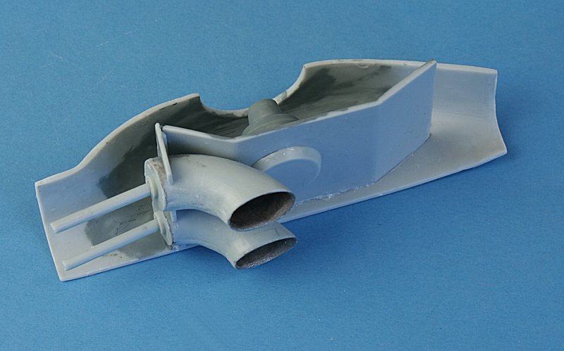
The difficult part is getting it all to line up - there is no construction sequence on the instruction sheet - just an exploded diagram.
I fitted the 'platform' into one nacelle half, assembled the jetpipes - and dry-fitted them into their bulkheads, so they 'floated'.....
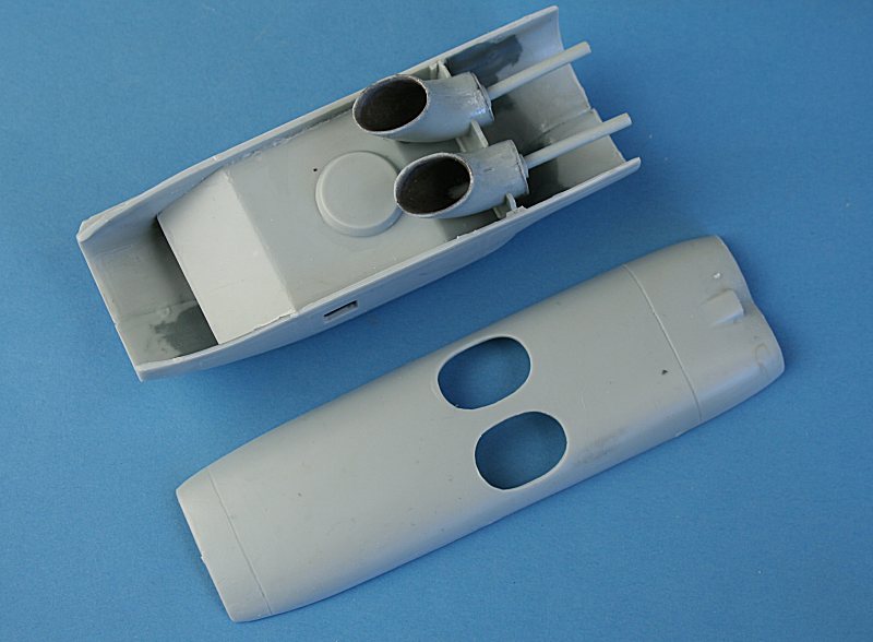
...after glueing the other nacelle half in place, I could move the jetpipes so that they lined up with the apertures in the nacelle bottom section...
.... before glueing the jetpipes and the bottom section in place.
The front top section was added - and the intakes glued to the front piece ....
....before it was glued in place. Note the poorly fitting parts. Out with the filler....
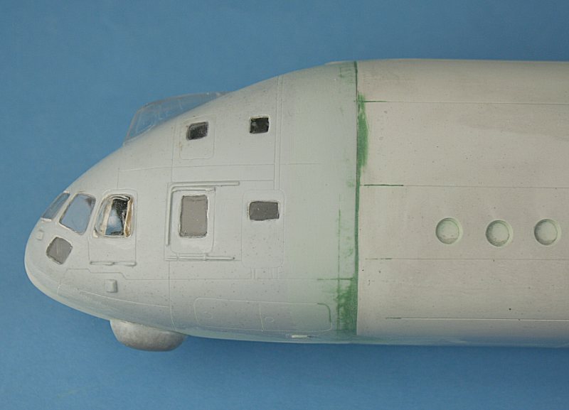
After fitting all the separate windows - and trimming ALL the openings and glazing to fit - they were cemented in place.
I have added curtains made from masking tape to the bubble windows.
The upper deck is supposed to be cemented to the lower and the whole lot just slides inside - at least that's what the instructions say!
In the above photos, I am test fitting the parts - but because of fit problems, I cemented the lower deck in place first - then cemented
both halves of the crew compartment together - then slid in the upper deck - after LOTS of 'fettling' to get it to fit!
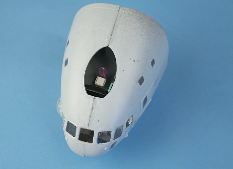
Here it is in place - showing the navigators seat in the upper 'balcony' - a clear cover goes on later. Note the poor fit of the windows and joints.
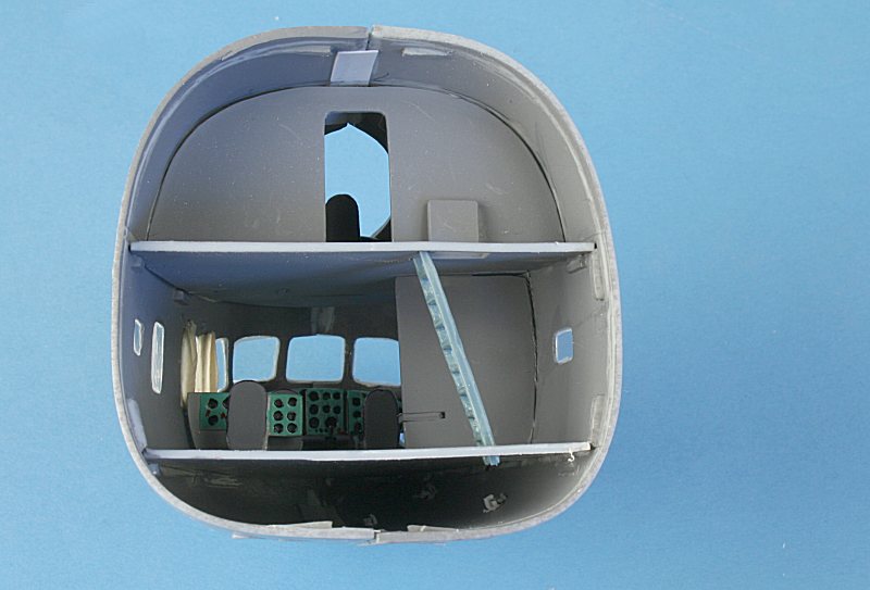
The crew compartment from the rear - note I have added plastic strip to strengthen the joints. All that interior detail is wasted....
.... because once the rear bulkhead is added, you can't see it anyway!
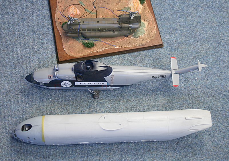
How big is a V-12?? - Chinook at top, Mil-26 Halo (the world's largest helicopter currently in service) - then the V-12 fuselage.
The cargo hold dimensions are 28.15m long by 4.4m wide by 4.4m high (92ft x 14.5ft x 14.5ft) - A C-5 Galaxy is 121ft x 19ft x 13.5ft.
Mil V-12 'Homer' next to a Mil Mi-26 'Halo'.
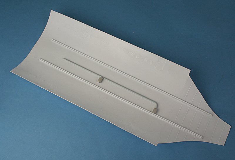
I added a couple of crane rails and some pipework to the vacform interior.....
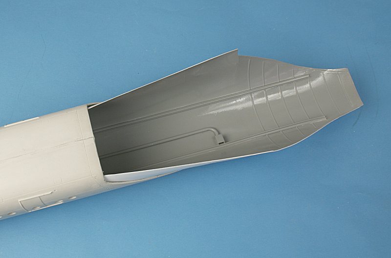
...before spraying it light grey and forcing into the fuselage. No gluing is required - tension keeps it in place.
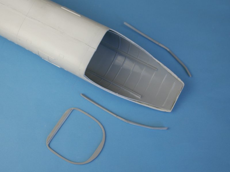
An injection-moulded frame plus a couple of edging parts completes the interior.
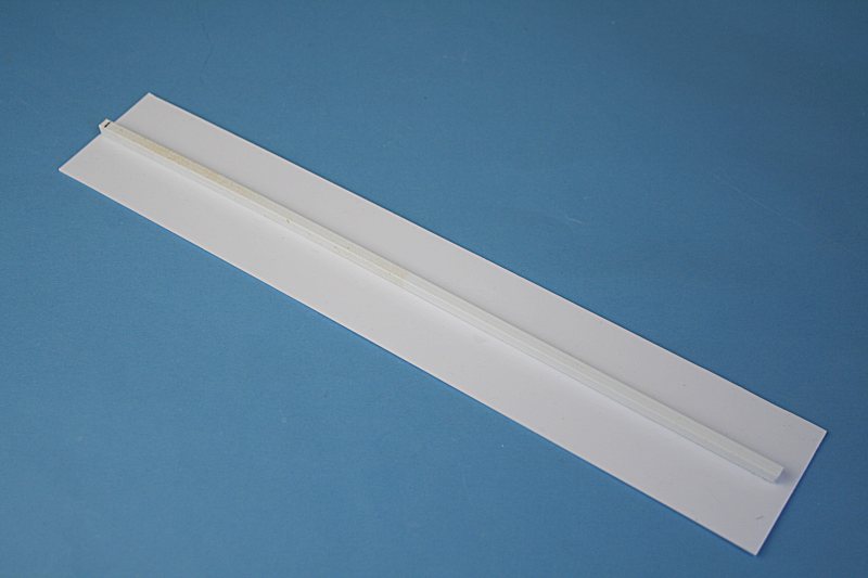
Amodel provide a length of thick plastic card for the floor. I did not added the provided bench seats, but did cement
a length of square-section plastic to provide rigidity. Sprayed dark grey, the floor slides inside the fuselage from the front.
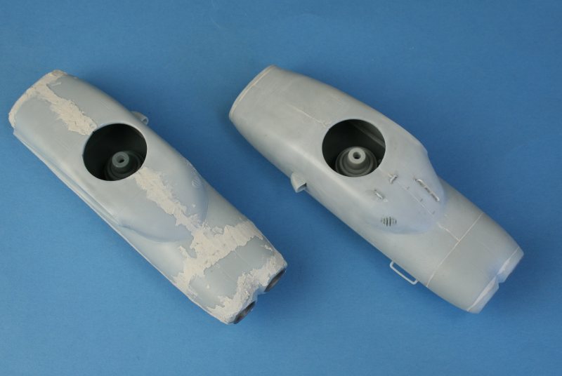
Lots of filler on the engine nacelles - all rubbed down on the right.
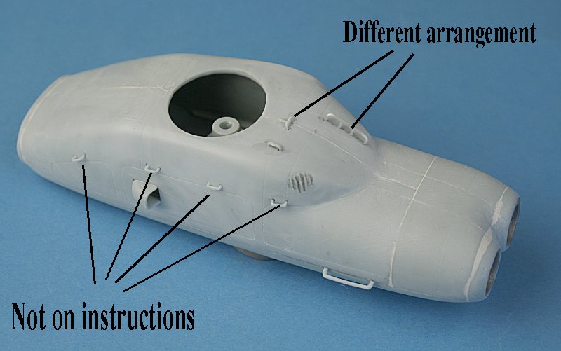
The arrangement of grab rails is wrong on Amodels instructions - I made my own long 'towel rail'
There are also four more grab rails provided on the sprue - but they are not shown on the instruction sheet.
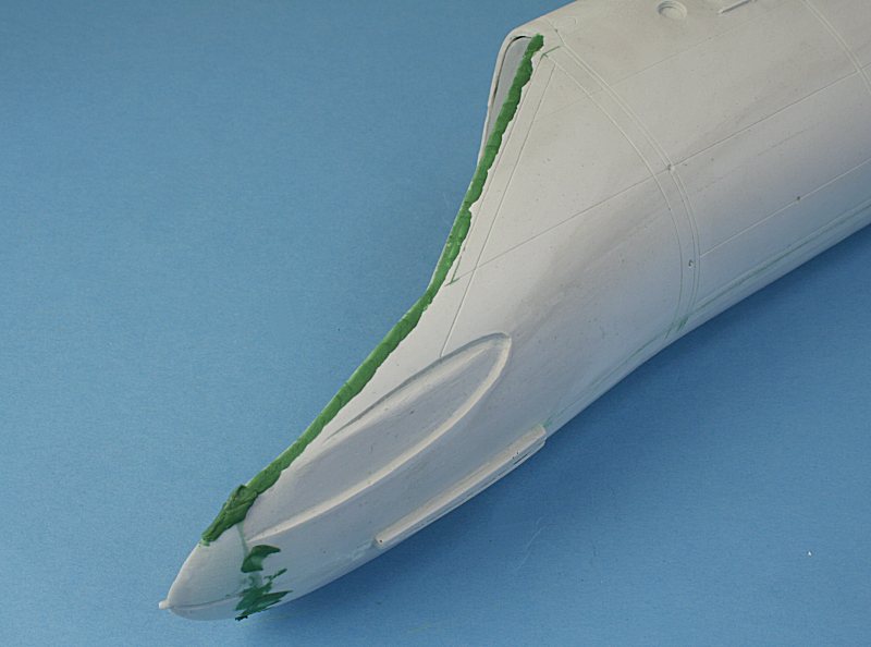
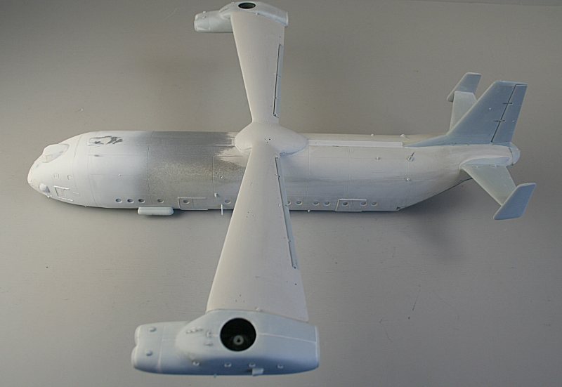
The fibreglass-resin fuselage cross-section does not quite match the injection-moulded nose section - so lots of filing, filling, sanding...
The rear end with the edging parts ......and the injected tailcone.
Lots of rubbing down later..........
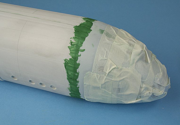
.....the panel lines are re-scribed and Tamiya masking tape applied.
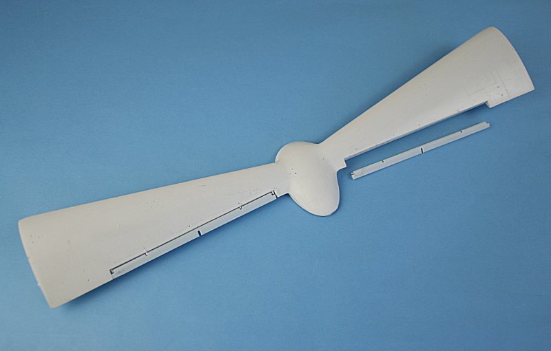
Injection-moulded flaps attached to fibreglass-resing 'wings'.
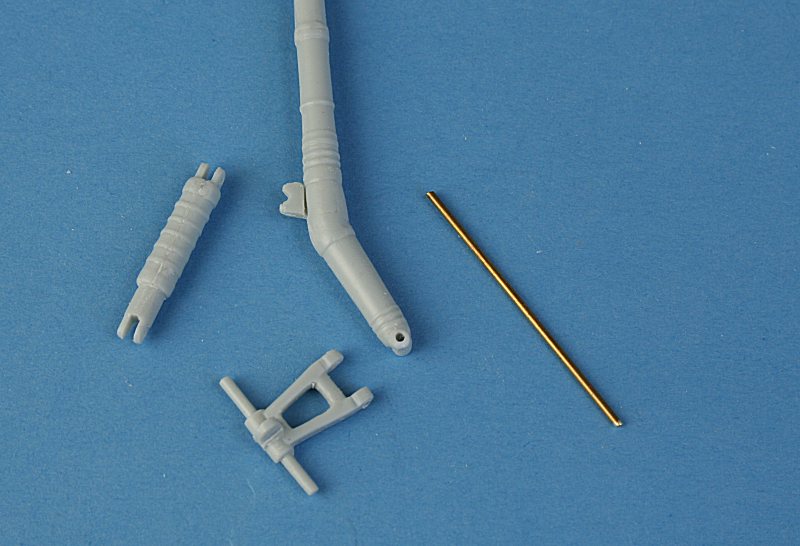
Undercarriage leg and pivoting axle part drilled out to accept brass rod .....
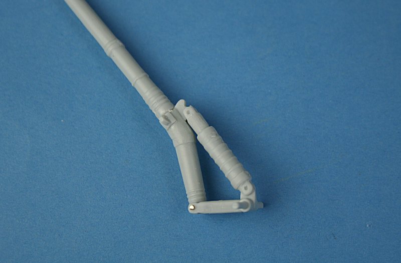
....to make the joint stronger.
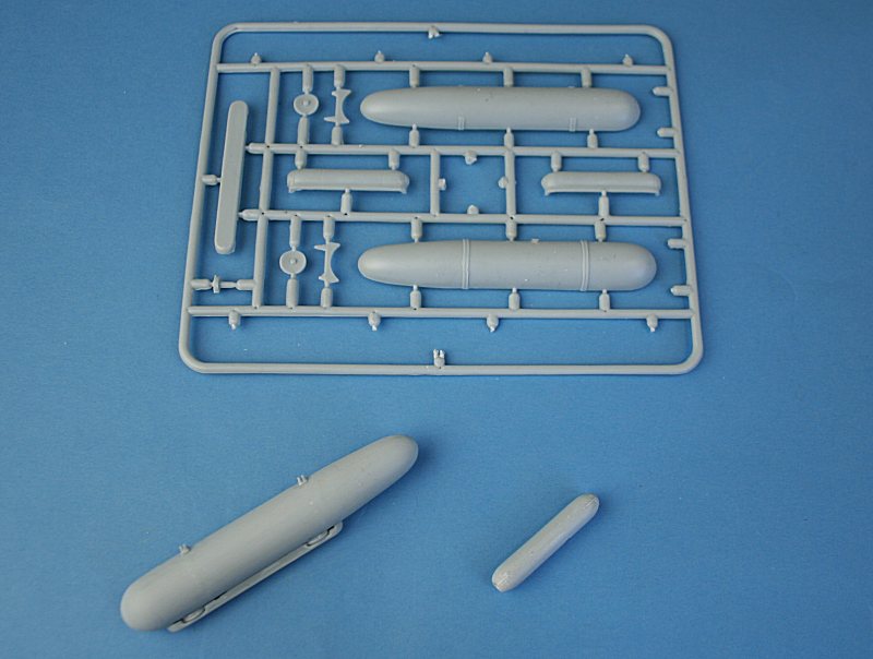
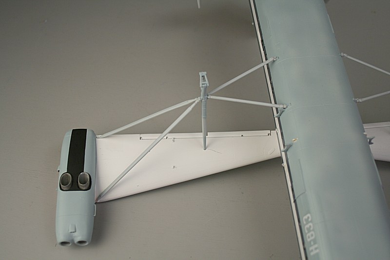
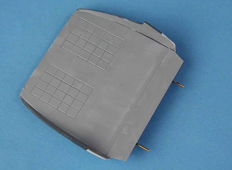
Parts and assembled fuel tank (left) and Heat Exchanger (right). I have removed the moulded-on straps from the fuel tank.
Fin, Heat Exchanger and mounting brackets attached....
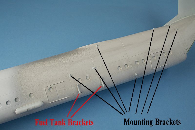
Lots of brackets to attach.
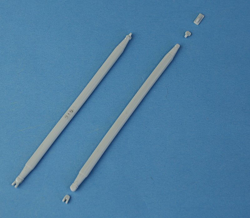
Strut & end 'fixings'.
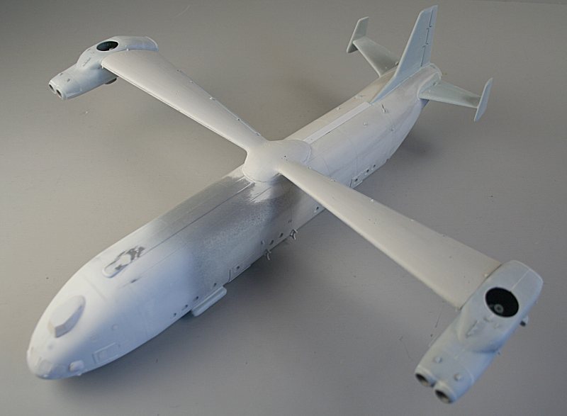
Model ready for its first primer coat.
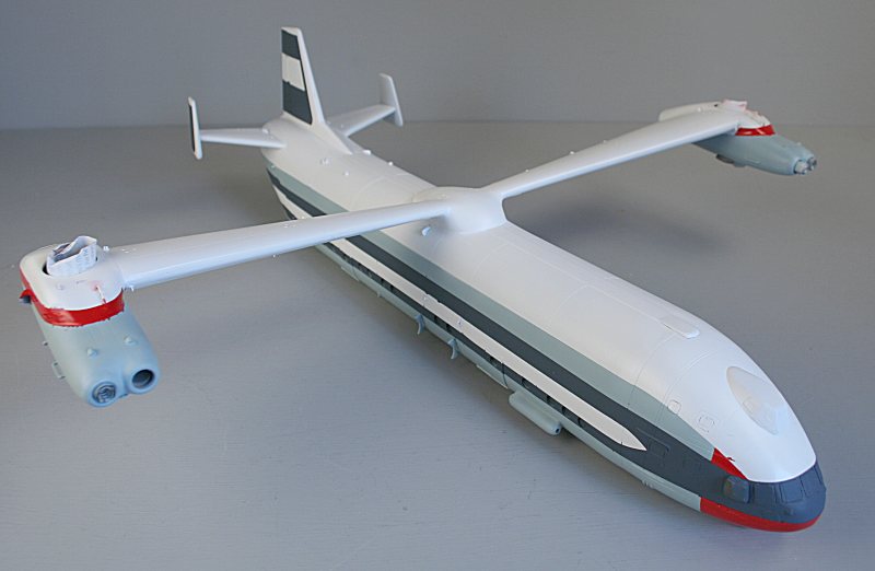
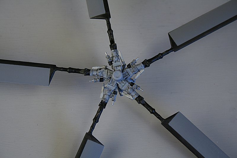
This thing is HUGE......
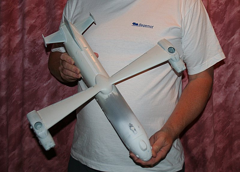
No, the V-12 is huge, not me!
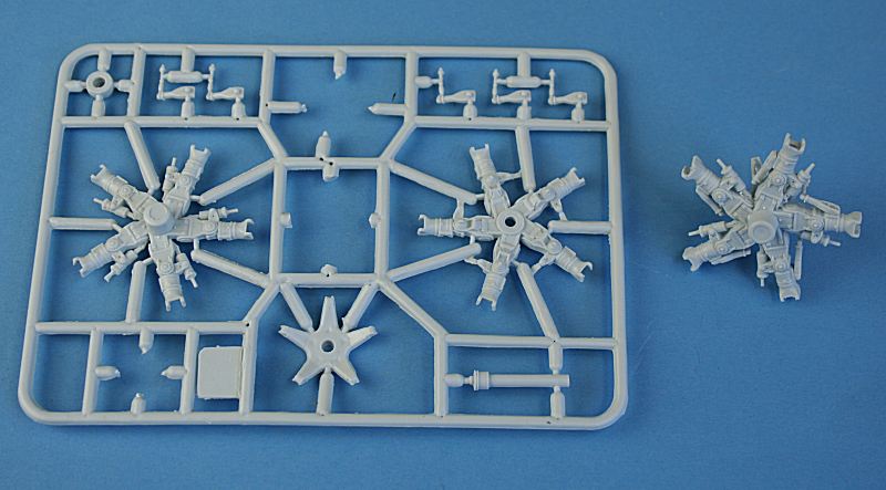
Parts for the main rotor hub - two sets of them (handed) taken from the Mil Mi-6. Ther completed hub is at right.
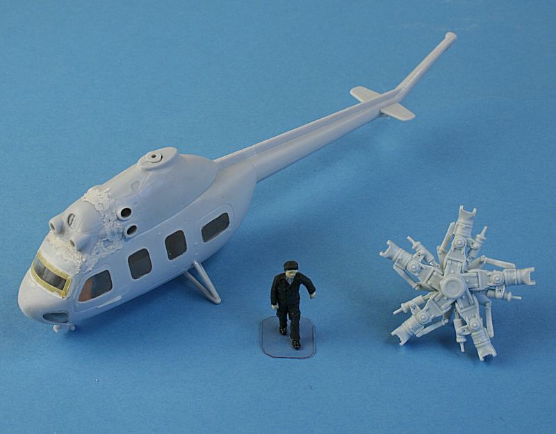
I am building a Mi-2 to go with my V-12 - here it is next to the rotor hub - with a 1:72 figure for scale.
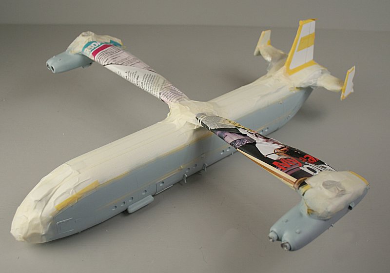
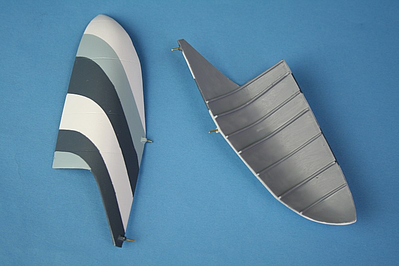
Painted white, masked, blue-grey applied. The fins are now masked up ready for the dark blue - the fuselage still needs to be masked.
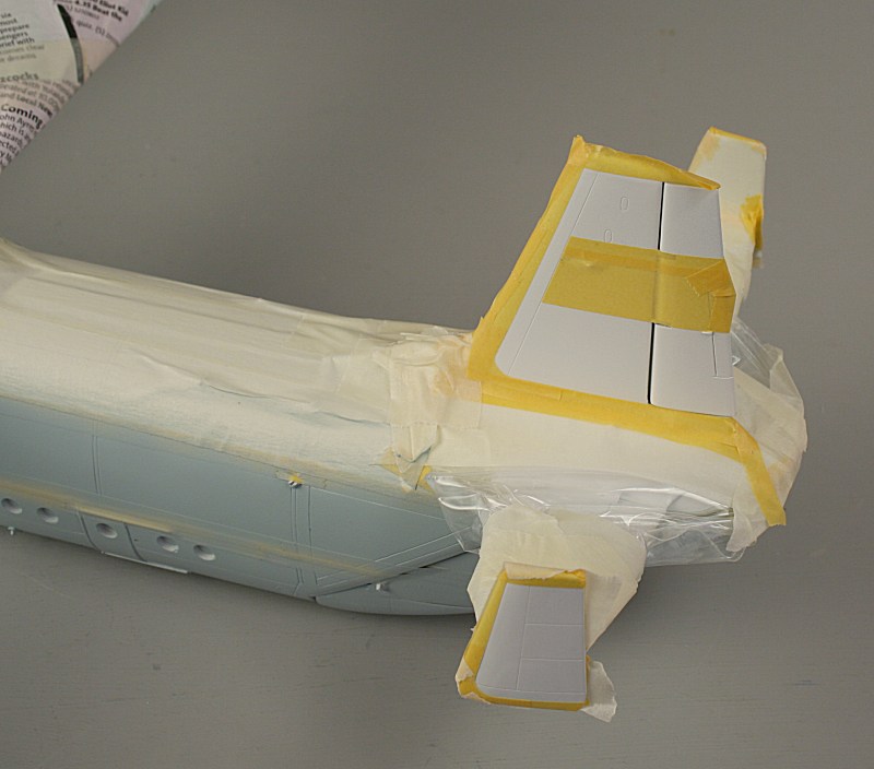
Home-made masks on the fins.
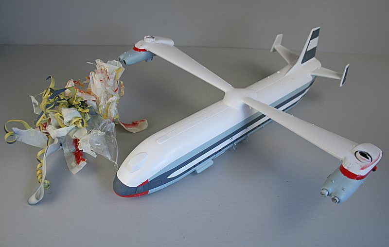
Mega masking, painting, masking, painting sessions - the final unmasking.....
Some paint runs to fix - particularly on the red!!
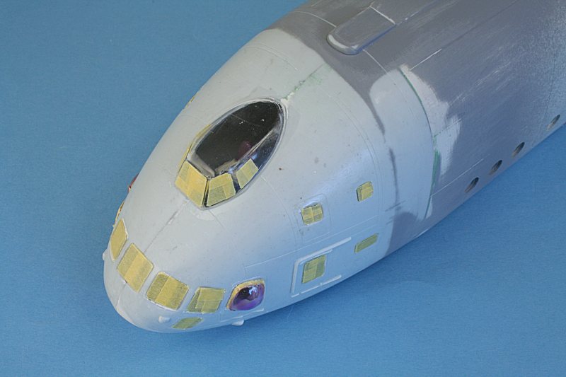
The windows are still masked.
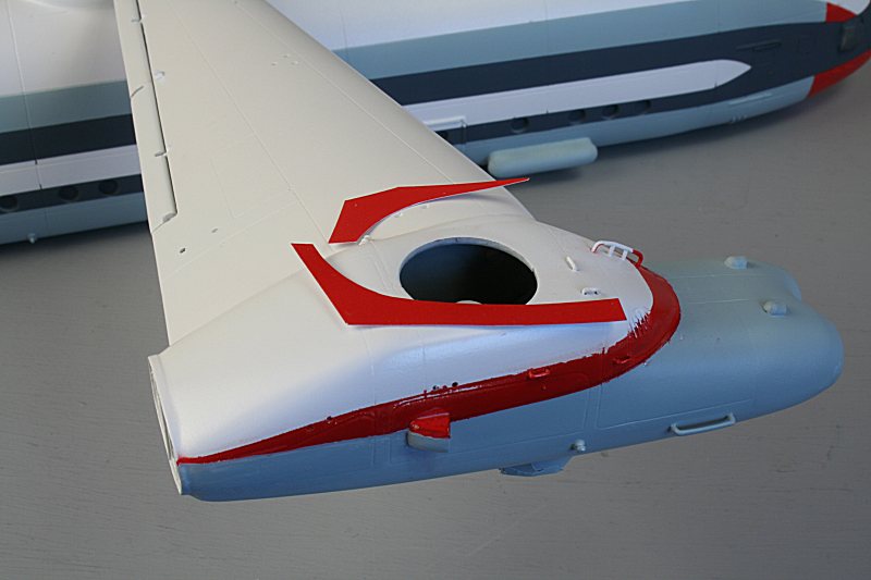
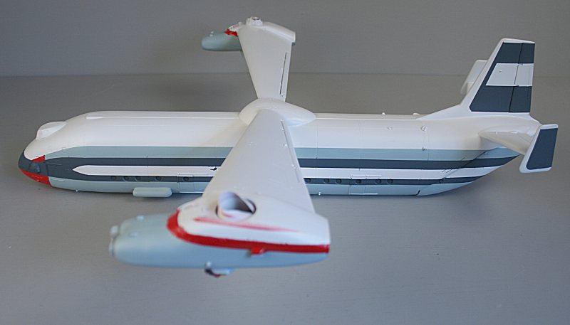
Repairs made to the red stripe using a combination of decal film and repainting....
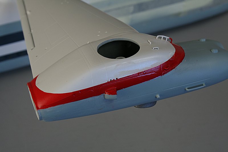
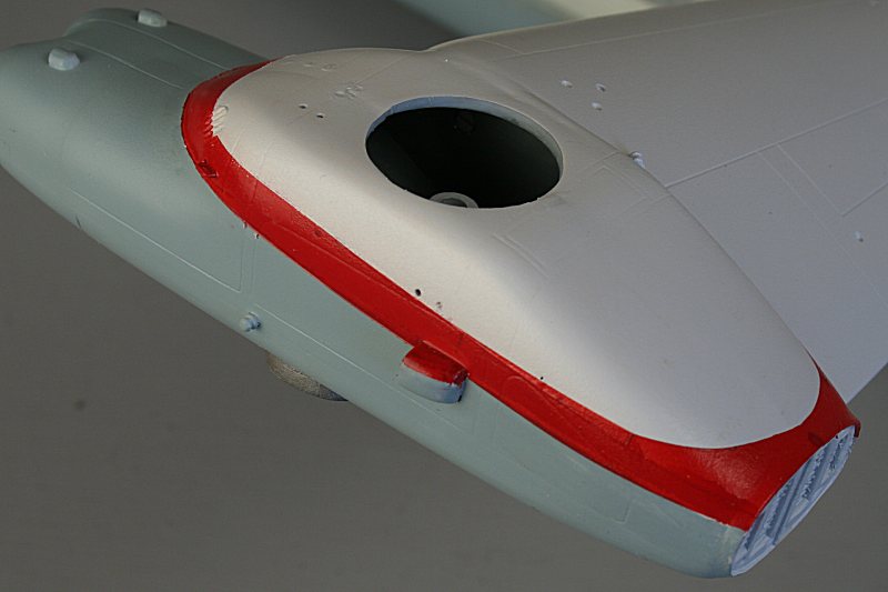
It looks much better now.
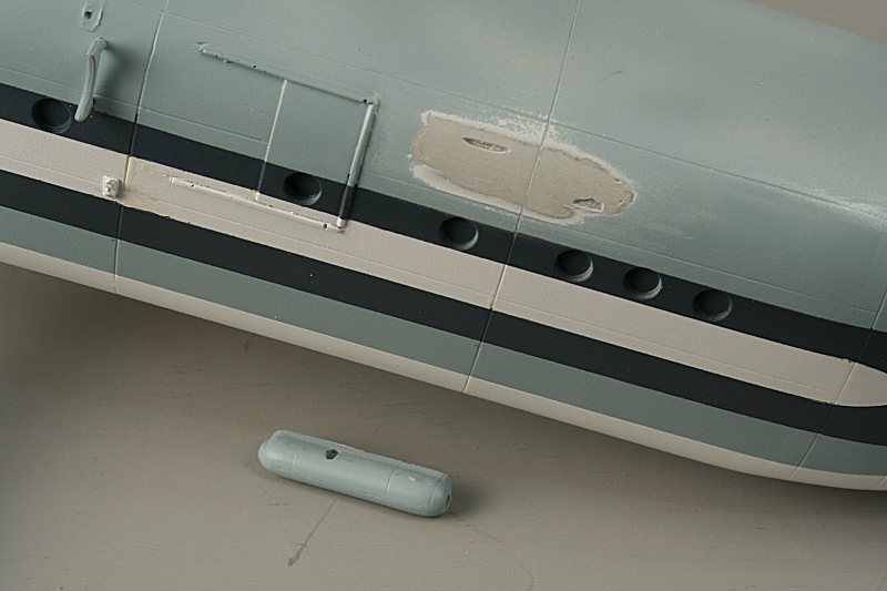
Damage to the resin fuselage where the heater has been snapped off.
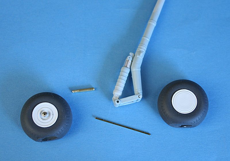
I have made brass rod & tube axles for the main wheels. Note the chrome strip for the piston section of the shock absorber.
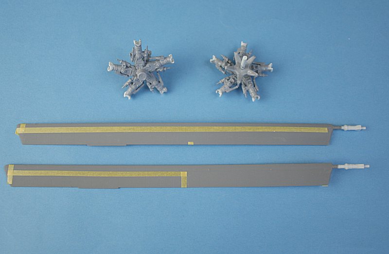
The rotor blades have to be masked masked - all ten of them - ready for painting the black areas.
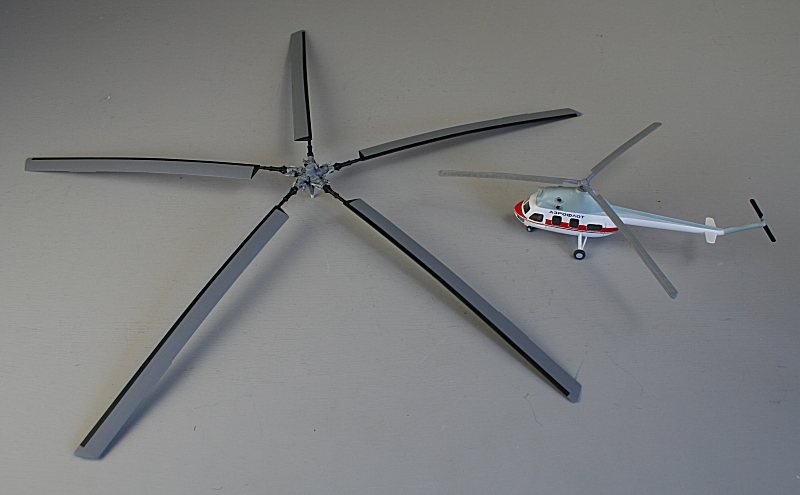
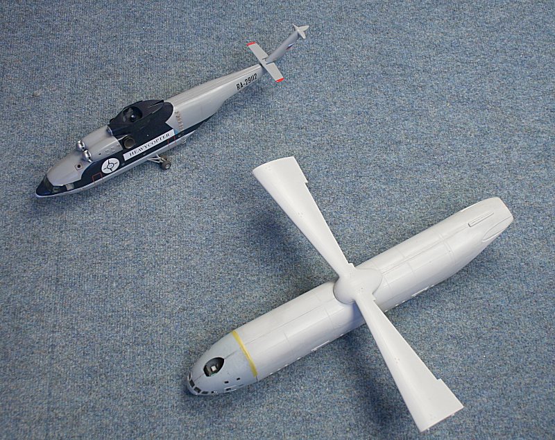
V-12 rotor next to a Mi-2 to lend scale.
The rotor hub is quite well detailed.
Starting to add the complex web of struts....
I have had to shorten some of the struts to make them fit......
Brass rod added to the clamshell doors for strength.....
.....and to the rear ramp.
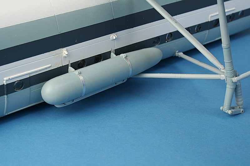
The fuel tanks do not fit in the intended position! The rear of the tank fouls the undercarriage leg support strut.
I have had to break off the tank mounting brackets and bodge it to fit the tanks higher up the fuselage.
The tank can't go any lower - because the strut is in the way.
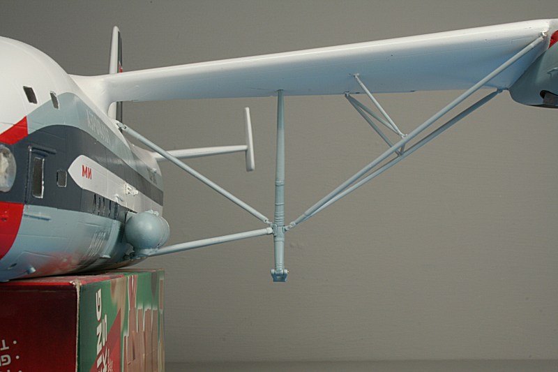
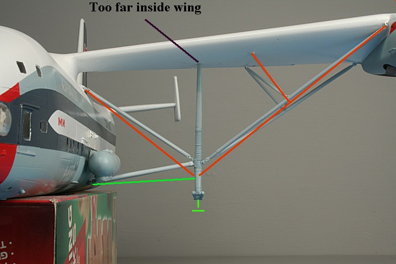
Green lines show where the bottom vee strut & axle should be - orange shows the struts I have shortened to fit!
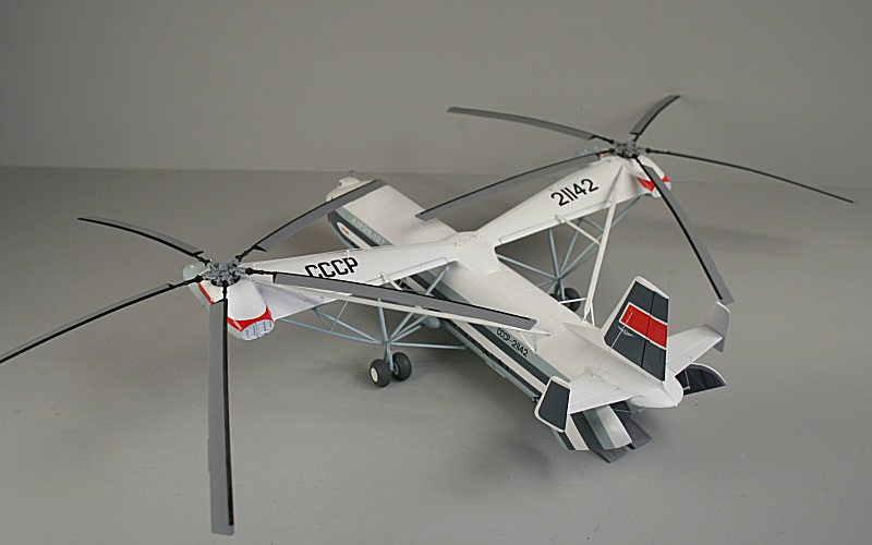
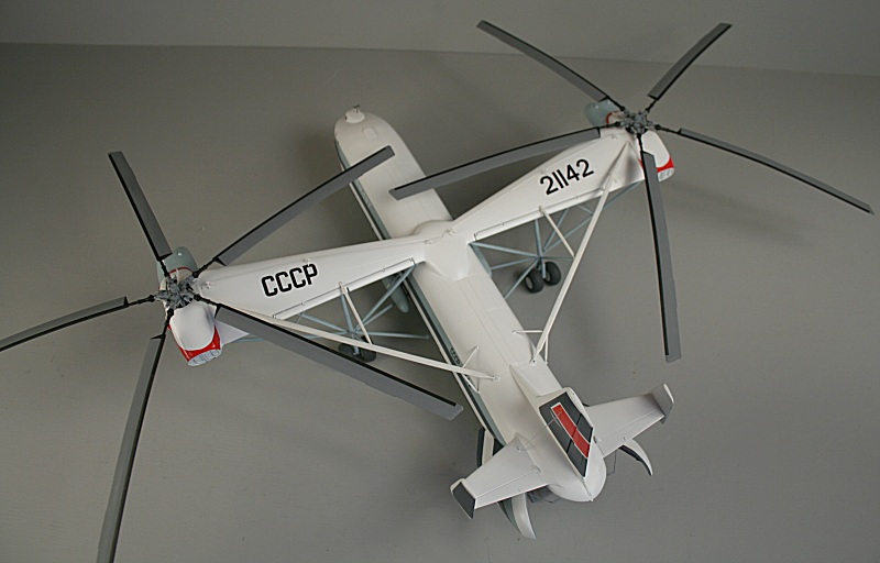
Finished!
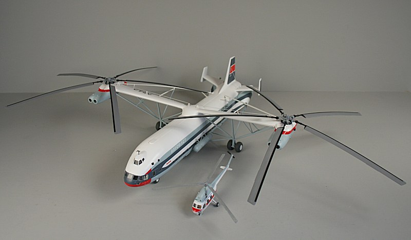
Finished V-12 next to a Mi-2 in the same scale.
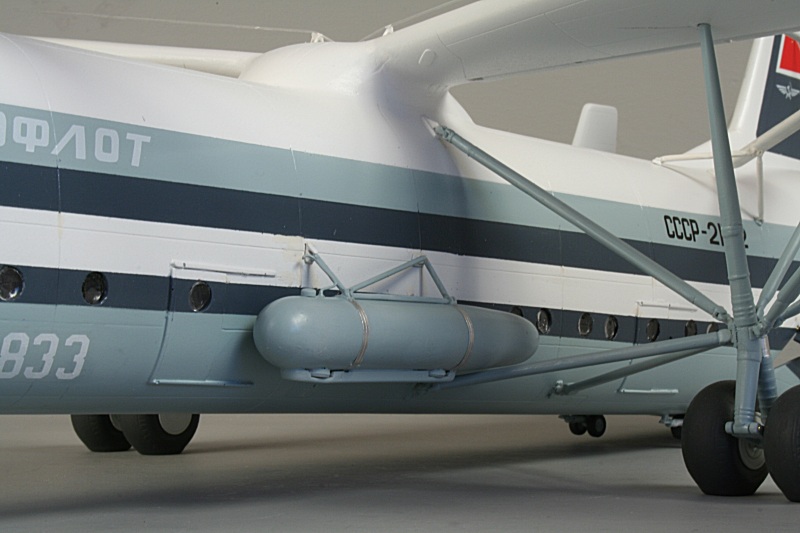
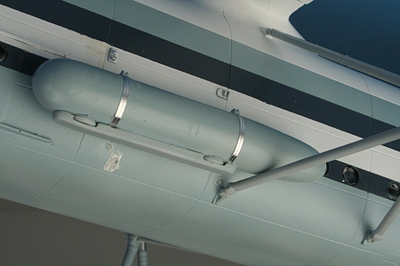
Fuel tank - with the addition of a filler cap and overflow pipe.
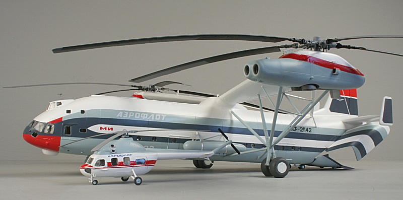
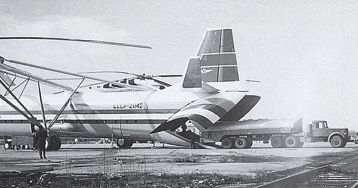
As the old Airfix ads used to say...... 'Just like the real thing!'.......
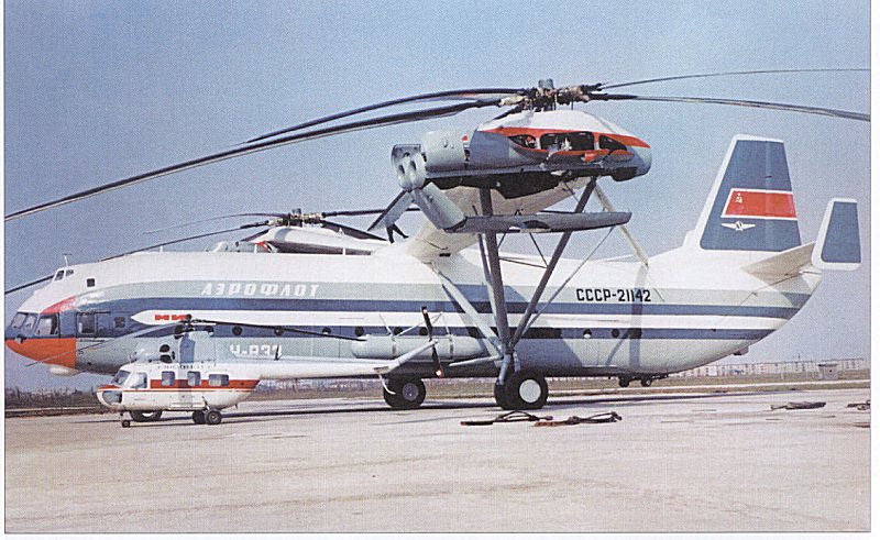
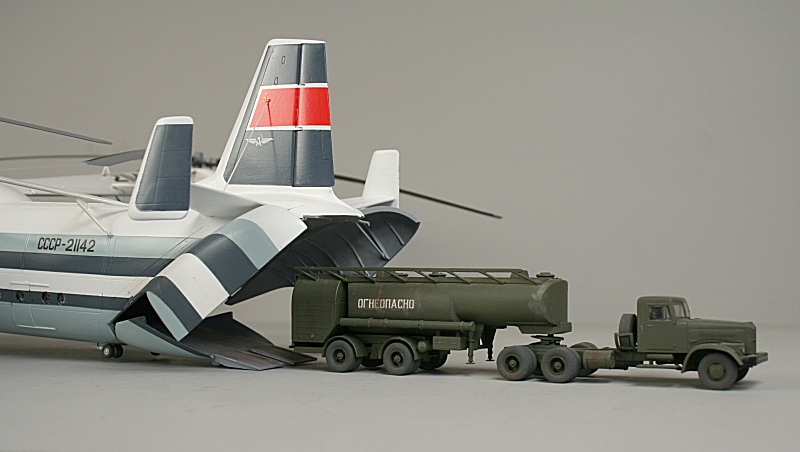
Just like the real thing - again..... KrAZ-258 refueller......
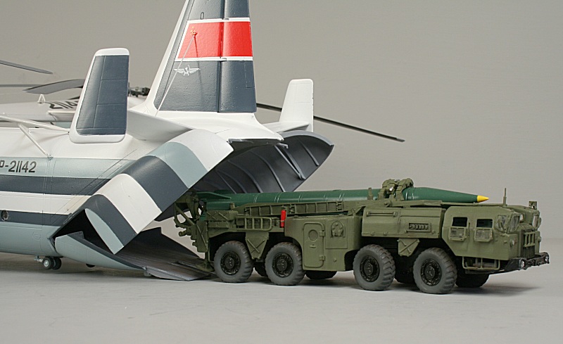
SCUD transporter.
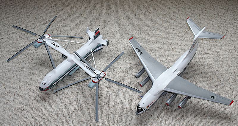
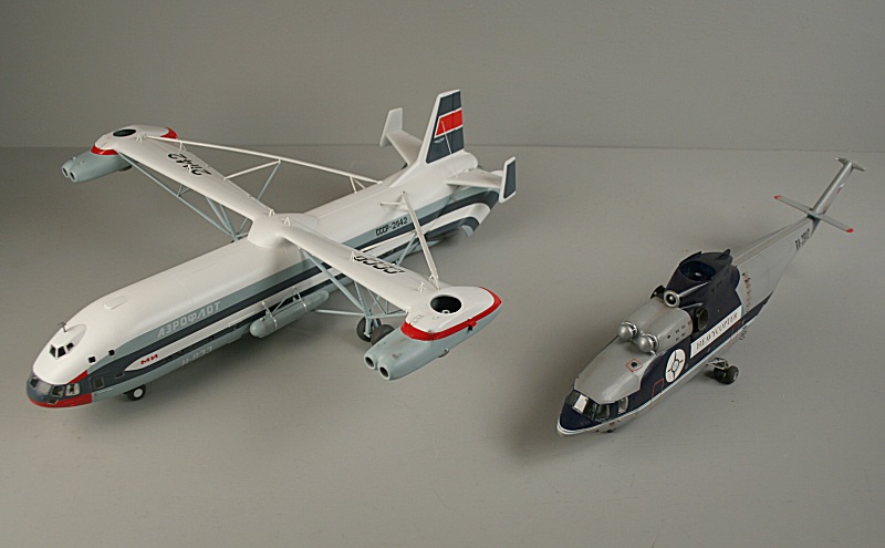
V-12 next to the Amodel Il-76 for size comparison.
V-12 next to its successor - the Mi-26 Halo.
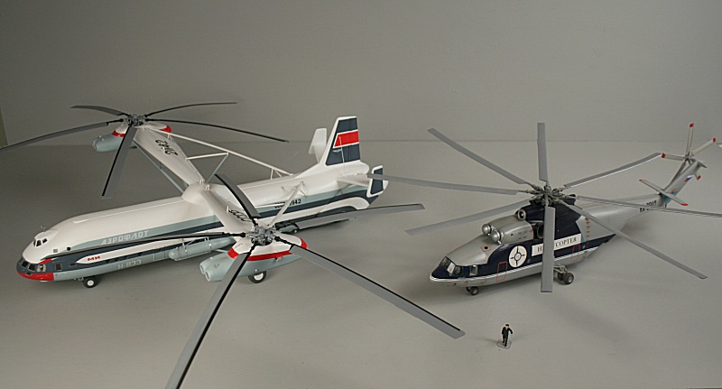
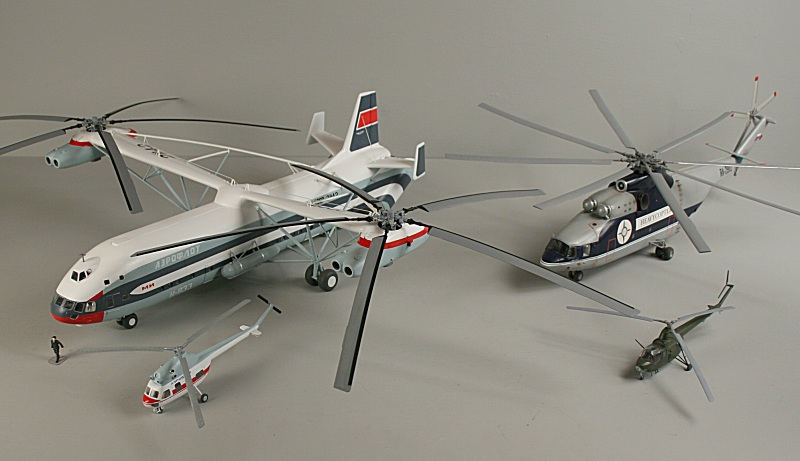
Mil collection - Mi-1, Mi-2, Mi-26 & V-12,
Ken Duffey
September 2008